Stoichiometric Ti3C2Tx Coating for Inhibiting Dendrite Growth in Anode-Free Lithium Metal Batteries
Abstract
Lithium metal batteries (LMBs) and anode-free LMBs (AFLMBs) present a solution to the need for batteries with a significantly superior theoretical energy density. However, their adoption is hindered by low Coulombic efficiency (CE) and rapid capacity fading, primarily due to the formation of unstable solid electrolyte interphase (SEI) layer and Li dendrite growth as a result of uneven Li plating. Here, we report on the use of a stoichiometric Ti3C2Tx (S-Ti3C2Tx) MXene coating on the copper current collector to enhance the cyclic stability of an anode-free lithium metal battery. The S-Ti3C2Tx coating provides abundant nucleation sites, thereby lowering the overpotential for Li nucleation, and promoting uniform Li plating. Additionally, the fluorine (−F) termination of S-Ti3C2Tx participates in the SEI formation, producing a LiF-rich SEI layer, vital for stabilizing the SEI and improving cycle life. Batteries equipped with S-Ti3C2Tx@Cu current collectors displayed reduced Li consumption during stable SEI formation, resulting in a significant decrease in capacity loss. AFLMBs with S-Ti3C2Tx@Cu current collectors achieved a high initial capacity density of 4.2 mAh cm−2, 70.9% capacity retention after 50 cycles, and an average CE of 98.19% in 100 cycles. This innovative application of MXenes in the energy field offers a promising strategy to enhance the performance of AFLMBs and could potentially accelerate their commercial adoption.
1 Introduction
Lithium-ion batteries (LIBs) have become one of the most prevalent energy storage devices in our society since their commercial introduction in the 1990s.[1, 2] However, constrained by the intercalation ion storage chemistry, LIBs struggle to meet the growing demand for higher energy density, particularly in emerging technologies such as drones and electric vehicles.[3-5] To address this need, researchers have turned their attention to Li metal anodes and lithium metal batteries (LMBs). Li metal anodes have a high theoretical capacity of 3860 mAh g−1 and a low redox potential of −3.040 V (vs the standard hydrogen electrode), and serve as a replacement for conventional anodes, such as graphite with the theoretical capacity of 372 mAh g−1, in LIBs.[6-9] Among all LMBs, anode-free lithium metal batteries (AFLMBs) have been proposed as a concept that could potentially achieve the ultimate theoretical energy density.[10, 11] AFLMBs do not initially include Li metal in the cell assembly; instead, Li metal is electroplated in situ on the anode current collectors. This configuration eliminates the need for an excess Li source and reduces manufacturing costs. Compared to conventional LIBs, AFLMBs can theoretically store 60% more energy per volume, positioning them as a promising solution for the next-generation energy storage technology.[12]
However, the practical commercialization of AFLMBs is hampered by low Coulombic efficiency (CE) and rapid capacity degradation. In situ-plated Li metal in AFLMBs is prone to side reactions during battery operation due to its high reducibility.[13] As a result, an inactive ionic conductive solid electrolyte interphase (SEI) layer is formed at the interphase of in situ-plated Li metal and electrolyte. The SEI layer formed, serves to protect the anode from the unwanted side reaction of Li metal and to minimize capacity loss during battery cycling.[14-16] However, the SEI layer undergoes multiple cracking and restructuring due to volume changes that occur during repeated cycling, resulting in the growth of Li dendrites and inactive Li, which are the primary causes of significant capacity loss. Therefore, several strategies have been explored to address the issue of unstable SEI in order to extend the cycle life of AFLMBs. These strategies can be categorized as electrolyte formulation optimization[10, 11, 17] and artificial SEI layer design.[18, 19] At the same time, it is important to emphasize the key role of the current collector in controlling dendrite growth and capacity loss. The morphology and chemical properties of the current collector significantly influence the Li metal growth. However, it has been widely reported that the Cu current collectors, which are generally accepted as current collectors in LIBs due to their chemical stability at low voltage, can easily cause random and uneven Li nucleation, leading to severe dendrite growth in AFLMBs.[20] As a result, much research has been devoted to the modification of current collectors. The modification methods are mainly focused on two categories: fabrication of 3D current collectors and application of lithiophilic coating.[20-25]
In the context of LMBs, several studies have reported that Ti3C2Tx and other MXenes exhibit uniformly distributed Li nucleation sites, promoting homogeneous Li metal growth on their surfaces.[26-28] MXenes are a family of 2D transition metal carbides, carbonitrides, and nitrides with a general formula of Mn+1XnTx,[29, 30] where M represents transition metals (such as Sc, Ti, V, Cr, and Mn), X represents carbon (C) and/or nitrogen (N), and n is an integer from 1 to 4. Tx signifies surface terminations such as –O, –OH, and –F that are introduced during the synthesis process. The application of MXenes is not limited to energy storage and harvesting;[31] they are also emerging materials with numerous applications, including optoelectronics,[32] electromagnetic interference shielding,[33] electro-, photo-, and chemical catalysis,[34] sensors,[35] and actuators.[36] This is due to their excellent electrochemical properties, electronic properties, and extraordinary mechanical and optical properties.[37] Furthermore, a modified stoichiometric Ti3C2Tx (S-Ti3C2Tx) was produced using excess Al in the MAX phase (S-Ti3AlC2) synthesis, which eliminates oxygen (O) impurities in the C layers of MAX and MXene.[38] It exhibits remarkably high conductivity and oxidation resistance, making it increasingly popular in scientific research.[39]
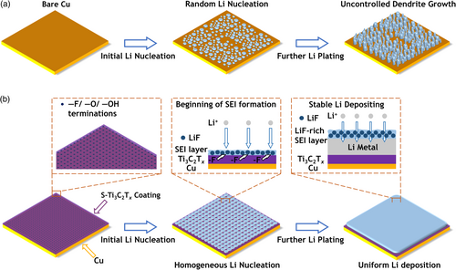
In this study, we report nanoscale spin-coating of S-Ti3C2Tx on the Cu current collector to form a LiF-rich SEI layer and promote more uniform Li plating, which mitigates uncontrolled Li dendrite growth in AFLMB. As illustrated in Figure 1, S-Ti3C2Tx@Cu offers abundant and uniformly dispersed fluorine (–F), oxide (–O), and hydroxyl (–OH) surface terminations that act as Li nucleation sites. As a result, S-Ti3C2Tx@Cu induces more homogeneous Li nucleation than Cu current collectors. During the Li plating process, –F terminations participate in the SEI formation, leading to the development of a LiF-rich SEI, which could reduce the SEI cracking and uncontrolled side reactions.[40-47] The use of S-Ti3C2Tx@Cu current collectors reduces the amount of Li required for SEI formation, resulting in improved battery performance. The AFLMB with S-Ti3C2Tx@Cu achieved high capacity retention of 70.9% after 50 cycles, compared to 29.2% after 50 cycles for the AFLMB with bare Cu current collectors. In addition, the AFLMBs with S-Ti3C2Tx@Cu achieved an impressive average CE of 98.19% over the course of 100 cycles.
2 Results and Discussions
S-Ti3C2Tx MXenes were synthesized by the minimally intensive layer delamination (MILD) method,[48] which involves selective etching of Al from the S-Ti3AlC2 MAX phase by in situ-generated HF from the etchant mixture—LiF and HCl. Details are provided in the Experimental Section. X-ray diffraction (XRD) patterns of S-Ti3AlC2 powder and S-Ti3C2Tx vacuum filtered film are shown in Figure 2a. The broad (002) peak, which corresponds to interlayer spacing between MXene layers, was observed to shift toward a lower angle, from 2θ = 9.5° to 6.1°. This shift results from the expansion of the average interlayer spacing from 0.93 nm to 1.45 nm. Upon removal of the Al layer from the MAX structure, the adjacent MX layers, which were previously bonded, lose their interconnectivity and undergo exfoliation, leading to an increased spacing close to 1.45 nm and a subsequent broadening of the (002) XRD peak. Notably, the XRD peaks indicating long-range order stacking along the z-axis of the MAX structure, in particular, the prominent (014) peak at ~38.7°, disappear after the exfoliation of the MXene. However, other (00z) peaks persist, confirming that the MAX phase has undergone complete exfoliation, resulting in the successful synthesis of 2D MXene structures.[49] The chemical species and stoichiometry/composition of S-Ti3C2Tx, as determined by X-ray photoelectron spectroscopy (XPS) are shown in Figure 2b,c and Figure S1, Supporting Information. In the Ti 2p spectrum (Figure 2b), S-Ti3C2Tx exhibits distinct peaks at 455.0, 455.5, 457.0, and 458.6 eV, corresponding to Ti–O, Ti–O/F, Ti–F, and TiO2, respectively.[50, 51] The XPS results, including C 1s (Figure S1a, Supporting Information) and O 1s (Figure S1b, Supporting Information), suggest that S-Ti3C2Tx contains Ti atoms in various chemical environments, which are covalently bonded to C and surface terminations such as –F, –O, and –OH. The FTIR spectrum (Figure S2, Supporting Information) further confirms the presence of different chemical species/surface terminations of S-Ti3C2Tx. Significantly, the F 1s profile reveals a notable peak of Ti–F at 685.0 eV, confirming the presence of –F termination of S-Ti3C2Tx, which plays a crucial role in the formation of the LiF-rich SEI. Furthermore, the chemical characterization confirms the advantages of S-Ti3C2Tx over the Ti3C2Tx synthesized from the conventional MAX phase (referred to as Con-Ti3C2Tx). A comparative XPS study of S-Ti3C2Tx and Con-Ti3C2Tx (Figure S14, Supporting Information) shows an elevated F element ratio of 10.77% for S-Ti3C2Tx, higher than the 7.42% recorded for Con-Ti3C2Tx. Meanwhile, the synthesized S-Ti3C2Tx exhibits a remarkably high electronic conductivity of 15 649 S cm−1, surpassing that of Con-Ti3C2Tx (9926 S cm−1) as shown in Figure S3, Supporting Information. A TEM image of a single flake of S-Ti3C2Tx of size larger than 2 μm is shown in Figure S4, Supporting Information. The cross-sectional SEM image of the S-Ti3C2Tx thin film prepared by vacuum-assisted filtration in Figure 2d displays its orderly alignment in stacked layers.
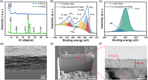
The fabrication of S-Ti3C2Tx@Cu involves a simple and low-cost process: spin-coating S-Ti3C2Tx solution onto the Cu substrate. Details of the spin-coating process can be found in the Experimental Section. The thickness of the S-Ti3C2Tx coating, as measured by the focused ion beam (FIB) and transmission electron microscopy (TEM) method, is about 42 nm (Figure 2e,f and Figure S5, Supporting Information). Digital photographs of S-Ti3C2Tx coatings at different times are additionally documented in Figure S6, Supporting Information. Despite its relative thinness, the S-Ti3C2Tx coating is sufficient to completely cover the Cu substrate. The uniformity of the S-Ti3C2Tx coating is further confirmed by the Energy Dispersive Spectroscopy (EDS) mapping in Figure S7, Supporting Information. In addition, the contact angle of 1,2-dimethoxyethane (DME), which serves as the electrolyte solvent, is smaller on S-Ti3C2Tx@Cu compared to Cu, as shown in Figure S8, Supporting Information. The reduction of the contact angle between DME and S-Ti3C2Tx@Cu to 7.0°, as opposed to the 47.8° observed between DME and Cu, suggests an improved wetting between the current collector and the electrolyte, which ensures the better electrochemical performance of the batteries.
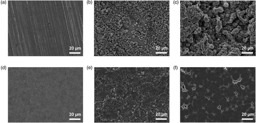
To study the Li plating morphologies on Cu and S-Ti3C2Tx@Cu current collectors, galvanostatic electrodeposition was performed. Coin cells were assembled with current collectors against Li metal as the electrode pair, and 1 м LiFSI +1 м LiNO3 in DME was used as the electrolyte. The selection of this electrolyte is attributed to the reparative effect of NO3− and the stability of Li metal in DME.[52, 53] And the operating current density was set to 0.5 mA cm−2. In particular, Cu and S-Ti3C2Tx@Cu current collectors exhibited significantly different Li deposition behaviors. As shown in Figure 3a,d, while the bare Cu surface shows sharp tracks from the cold rolling of Cu film, the surface of S-Ti3C2Tx coated on Cu is more homogeneous. The initial Li nucleation conditions were controlled at an areal capacity of 0.2 mAh cm−2. Due to the high nucleation energy required for Li ions to deposit on Cu, the Li ions tend to deposit on Li metal rather than Cu, resulting in irregular and loosely structured Li nucleation on Cu current collectors, as shown in Figure 3b. Conversely, the surface terminations of S-Ti3C2Tx significantly reduce the desired nucleation energy for Li ions,[27, 28] resulting in the formation of well-spread and uniform Li nucleation sites as illustrated in Figure 3e. Uniform and well-dispersed Li nucleation effectively mitigates the possibility of uncontrolled and rampant dendrite growth. After Li plating at 4 mAh cm−2, the Cu current collectors experience loose Li plating with severe Li dendrites, as shown in Figure 3c. This can be attributed to deficient Li nucleation. The extensive dendrite growth can easily cause some dendritic Li metal to detach from the Li anode, making it inactive because of the fully covered SEI, and hence, not participating in electrochemical reactions, a phenomenon referred to “dead Li.”[12] Simultaneously, the loose Li metal deposition possesses dramatically expanded surface area. This expansion, combined with the continuous forming and disruption of SEI, involves utilization of substantial amount of Li into SEI formation, leading to rapid capacity loss and a curtailed cycle lifespan.[11, 12] In contrast, the Li metal deposition on S-Ti3C2Tx@Cu is dense and smooth (Figure 3f), indicating significant advantage over Li plating on Cu. In addition, a high current density of 4 mA cm−2 was used to characterize the morphology of Li nucleation and plating. As shown in Figure S9, Supporting Information, Li nucleation decreases in size and becomes more densely packed.[54] Importantly, the favorable performance of S-Ti3C2Tx@Cu is consistent with the observations in Figure 3. Moreover, we compared the morphology of the stripped Li on the current collectors (Figure S10, Supporting Information). After the first cycle, stripped Li forms clusters on Cu due to uneven Li plating. Conversely, it appears more planer on S-Ti3C2Tx@Cu. Even after 100 cycles, the stripped Li remains more homogeneous on S-Ti3C2Tx@Cu than on Cu. These results further confirm the superiority of S-Ti3C2Tx in facilitating stable Li plating and stripping processes.
The remarkable improvement of S-Ti3C2Tx@Cu over Cu current collectors can be attributed to the different SEIs formed on the in situ-deposited Li metal on S-Ti3C2Tx@Cu and Cu current collectors. The terminations of S-Ti3C2Tx are actively involved in the SEI formation. In particular, the –F terminations contribute to the LiF content, which increases the overall stability of the SEI and thus promotes efficient Li cycling. In order to elucidate the composition of the SEIs and the influence of the S-Ti3C2Tx terminations on SEI formation, in-depth XPS was performed, revealing conditions deep within the material rather than just at the surface. Specifically, this comprehensive characterization was performed on a sample with Li plating of 4 mAh cm−2 formed on different current collectors, achieved at a current density of 0.5 mA cm−2. The depth of characterization was controlled by sputtering for 480 s, with data being recorded every 60 s.
From the quantified atomic composition ratios of the Li metal surface on Cu (Figure 4a), it is evident that the elements Li, O, and C are from the primary composition of SEI on Cu after Li plating. In contrast, the main components of the S-Ti3C2Tx@Cu (Figure 4d) after Li plating are the elements Li, O, and F elements. The most notable difference between the SEIs is the F content. Due to the involvement of the –F termination of S-Ti3C2Tx in SEI formation, the F ratio in S-Ti3C2Tx@Cu is significantly higher, ranging from 16.43% to 25.81%, compared to that of Cu, which ranges from 5.00% to 9.73%. At the same time, the S ratios in the SEIs are nearly identical, indicating a similar degree of LiFSI salt decomposition in the different SEI formations. This similarity, combined with the observation that the LiF content decreases with depth, supports the notion that the elevated F content is due to S-Ti3C2Tx rather than LiFSI decomposition.[26] The F 1s XPS spectra (Figure 4b,e) provide further insight into composition of the SEI. Considering the presence of LiNO3 in the electrolyte salts, the decomposition of LiFSI is more comprehensive, and most F is attributed to LiF (685.0 eV).[53] In addition, the LiF peak in the SEI of S-Ti3C2Tx@Cu after plating is remarkably higher than that of Cu, demonstrating the promotion of LiF in the SEI induced by the S-Ti3C2Tx coating. The peak at 688.0 eV corresponds to the presence of LiFSI residue on the surface of SEI.
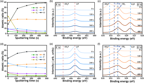
Another notable difference is observed in the C element ratios within the SEI. The C ratio in the SEI of Li deposition on S-Ti3C2Tx@Cu remains low, not exceeding 7%. In contrast, the C ratio in the SEI of the Cu current collector reaches 33.2% at the outer SEI, indicating additional DME electrolyte decomposition, which may affect the electrolyte stability. The other major element, O, in the SEI on Li plating of Cu is at most ~5% higher than that of S-Ti3C2Tx@Cu. Detailed distinctions can be interpreted from the O 1s XPS spectra (Figure 4c,f). The peaks of Li2O (528.0 eV) are similar in both cases. The variation is due to LiSOx (531.2/532.1 eV) decomposing from LiFSI. Coupled with the S 2p XPS profile (Figure S11a,c, Supporting Information), it is clear that in the absence of S-Ti3C2Tx, the main decomposition products of LiFSI are SO32− (167.0/168.1 eV) and SO42− (168.8/169.9 eV). It is noteworthy that S-Ti3C2Tx leads to an increased fraction of SO42−. The peak at 160.0 eV represents the presence of Li2S. The peaks found at 533.3 eV in the O 1s XPS spectra and 170.2 eV in the S 2p XPS spectra are all attributed to the LiFSI residue. Furthermore, in the N 1s XPS spectra (Figure S11b,d, Supporting Information), the absence of S-N (400.0 eV) in the inner layer of SEI confirms the complete decomposition of LiFSI.[55, 56] The presence of LiSOx in SEIs can contribute to the uniformity of the SEI and Li deposition,[53] whereas the increased LiF content induced by S-Ti3C2Tx ensures long-term cycling stability. Upon characterization of the SEI, it becomes clear that the LiF-rich SEI, induced by S-Ti3C2Tx, creates extensive volume grain boundaries of LiF/Li2O. These boundaries provide a multitude of open channels that facilitate rapid Li ion diffusion.[57] In addition, the simultaneous presence of LiSOx, Li2S, and LiNxOy creates a synergistic effect of these components, further stabilizing the interphase.[53, 58] Furthermore, no peaks are observed in the Ti 2p XPS spectra (Figure S12, Supporting Information), indicating the absence of Ti–C bonding in the SEI.
To validate the above assumption, the electrochemical performance of Cu/Li and S-Ti3C2Tx@Cu/Li asymmetric cells was characterized. The profiles of the galvanostatic Li metal plating are shown in Figure 5a, where a cutoff capacity of 0.5 mAh cm−2 is set at an areal current density of 50 μA cm−2. The profile highlights a reduced Li metal nucleation overpotential (~31 mV) in contrast to that of Cu (~ 50 mV), providing evidence for the lower energy barrier for nucleation at the Li nucleation sites on the S-Ti3C2Tx surface. To investigate the long-term performance of the asymmetric cells, Cu/Li and S-Ti3C2Tx@Cu/Li batteries were set to discharge to a fixed capacity of 1 mAh cm−2 and charged to 2 V to strip the Li at an elevated current density of 0.5 mA cm−2 over several cycles. During the initial cycle (Figure 5b), S-Ti3C2Tx@Cu shows a similar trend of lower nucleation overpotential as seen in Figure 5a. Meanwhile, due to the uniform nucleation and plating in the first cycle, S-Ti3C2Tx@Cu shows a significant improvement over Cu of CE (85.07% vs 64.45%). This advantage is maintained in subsequent cycles (Figure 5c), with particularly remarkable results in the first 20 cycles. Although the capacity loss in the first cycle is mainly due to the SEI formation, S-Ti3C2Tx@Cu consistently maintains CE above 96%, a feat that Cu can only achieve after 20 cycles. It is important to note that batteries with Cu current collectors tend to suffer from an unstable SEI until after these 20 cycles, and only then are able to operate stably. On the other hand, S-Ti3C2Tx@Cu is able to reduce the Li consumption required to induce a stable SEI and to recover from stable SEI in a few cycles, thereby saving a significant amount of capacity and improving the cycling performance of the battery. It was observed that the average CE of S-Ti3C2Tx@Cu asymmetric cell is 97.51% for over 100 cycles, superior to that of Cu (95.88%).
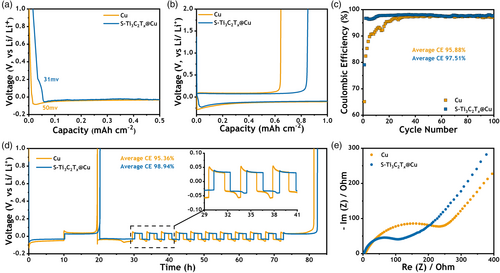
In addition, Aurbach CE tests[59] were performed to evaluate the Li cycling efficiency on the plated Li substrate. In this method, 5 mAh cm−2 of Li was first deposited and fully stripped to 1 V as a preconditioning process to avoid the influence of low initial CE on the average CE measurement. Subsequently, 5 mAh cm−2 of Li was plated as a Li reservoir, followed by a fixed capacity density of 1 mAh cm−2 stripping/plating for 10 cycles. All remaining Li was then stripped, and the stripping capacity was recorded. The operating current density is 0.5 mA cm−2. The calculation method of the average CE is explained in the Experimental Section. The battery equipped with the S-Ti3C2Tx@Cu current collector exhibited a superior average CE of 98.94%, significantly outperforming that of the Cu variant (95.36%), as shown in Figure 5d. At the same time, the S-Ti3C2Tx@Cu cell shows reduced Li nucleation on the current collectors. From the magnified profile illustrating the cycling voltage of the stripping/plating process, it also shows lower polarization than Cu-based batteries. These effects can be attributed to the stable interfacial structure between Li metal and electrolyte, facilitated by S-Ti3C2Tx. Following the Aurbach CE test, we conducted electrochemical impedance spectroscopy (EIS) on the cells. Notably, the cells utilizing S-Ti3C2Tx@Cu exhibited a reduced impedance of 117 Ω, whereas those employing Cu showed an impedance of 173 Ω. This improved cycling stability and lower impedance is a consequence of the LiF-rich SEI formed due to S-Ti3C2Tx, corroborating the SEI analysis results.
In order to carefully investigate the effect of –F terminations of S-Ti3C2Tx in inducing LiF-rich SEI layer and improving battery cycle life, we also investigated Con-Ti3C2Tx in this study. Figure S13a, Supporting Information, shows the XRD patterns of conventional MAX phase and Con-Ti3C2Tx, and the SEM image of the Con-Ti3C2Tx film is shown in Figure S13b, Supporting Information. It is evident that the structural characterization of Con-Ti3C2Tx closely matches that of S-Ti3C2Tx. The primary discrepancy between two MXenes prepared from two different MAX phases is the elemental ratio, which is shown in Figure S14a, Supporting Information. The Ti: C of S-Ti3C2Tx is inferior to that of Con-Ti3C2Tx, in agreement with the reports of S-Ti3C2Tx.[39] Interestingly, we observed that the F ratio of S-Ti3C2Tx, synthesized by the MILD method, is marginally higher. The C 1s and F 1s XPS spectra are shown in Figure S14b,c, Supporting Information, respectively. A similar LiF content in the SEI layer was also detected in Figure S15, Supporting Information. Due to the lower –F termination content and consequently lower LiF content in the SEI, the average CE in the Aurbach CE test of the Con-Ti3C2Tx battery is 97.41% (Figure S16a, Supporting Information). While the CE is slightly lower compared to S-Ti3C2Tx (98.94%), it still exceeds the CE of Cu batteries (95.36%).
Additionally, we compared the battery performance of the free-standing S-Ti3C2Tx vacuum-filtrated film without a Cu current collector and S-Ti3C2Tx@Cu current collector. With a higher accessible surface area, the S-Ti3C2Tx vacuum-filtrated film without a Cu current collector involves more Li source in the formation of SEI, which consequently leads to lower capacity retention in the first cycle,[60] as shown in Figure S17, Supporting Information, (with a retention of 81.98%, compared to the 85.07% exhibited by the S-Ti3C2Tx@Cu). The smooth surface of S-Ti3C2Tx@Cu reduces the possibility of dendrite growth, unlike the S-Ti3C2Tx vacuum-filtrated film without a Cu current collector.[61] While, the need to withstand substantial volume changes in AFLMBs cycling makes S-Ti3C2Tx@Cu current collectors more suitable for this application.
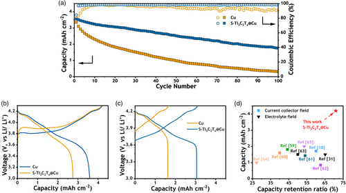
Moreover, to verify the improved cyclic stability of S-Ti3C2Tx@Cu in a practical battery configuration, the anode-free coin cells were assembled with NCM811 paired with S-Ti3C2Tx@Cu and Cu current collectors. The detailed components and relative amounts are given in the Experimental Section and Table S1, Supporting Information. The batteries were operated in the voltage window from 3.0 to 4.3 V, the current density is 0.84 mA cm−2, corresponding to 0.2C rate. Figure 6a displays the capacity retention and CE of the AFMLBs during the working cycles, which apparently illustrate the superiority of S-Ti3C2Tx@Cu. In the first cycle (Figure 6b), the initial charge of all AFLMBs could reach 4.2 mAh cm−2 due to the high energy density of the NCM811 cathode material. The first cycle discharge capacity of the cell with Cu current collectors is 2.75 mAh cm−2, with only ~66% of the capacity remaining. However, taking advantage of the high Li utilization efficiency of S-Ti3C2Tx@Cu, the first cycle capacity retention of S-Ti3C2Tx@Cu is 3.55 mAh cm−2 (~84%). The battery with S-Ti3C2Tx@Cu maintains higher CE in all the cycles (Figure 6a), especially in the first few cycles. The initial uniform and smooth lithium plating contributed to stable performance in subsequent cycles. After 20 cycles, the capacity of the cell with S-Ti3C2Tx@Cu is still maintained (3.10 mAh cm−2 for charging), while that of Cu is already reduced to 1.67 mAh cm−2. S-Ti3C2Tx@Cu AFLMB displays 70.9% remaining capacity after 50 cycles. Compared to previously reported studies on initial capacity and capacity retention after 50 cycles, our results are consistent with previous investigations and show greatly enhanced performances (as depicted in Figure 6d).[62-68] Detailed information on these referenced studies can be found in Table S2, Supporting Information. After 100 cycles, the S-Ti3C2Tx@Cu AFLMB still has 49.6% Li capacity remaining. The average CE of the S-Ti3C2Tx@Cu AFLMB is 98.19% after 100 cycles, compared to 95.23% of the AFLMB with Cu. In addition, Con-Ti3C2Tx@Cu achieves 65.67% capacity retention after 50 cycles with a CE of 97.97% over 100 cycles (Figure 16b).
3 Conclusions
In this work, we propose a novel S-Ti3C2Tx coating on a Cu current collector that enables homogeneous Li plating and enhances the Li cycling efficiency and lifespan of AFLMBs. The presence of surface terminations (such as –O, –OH, and –F) provides abundant nucleation sites, resulting in a reduced overpotential for Li nucleation. This reduction in overpotential promotes the occurrence of uniform Li nucleation during the initial stages of Li plating, resulting in uniform and smooth coverage of S-Ti3C2Tx@Cu. Moreover, we found that the –F terminations of S-Ti3C2Tx actively participate in the formation of LiF-rich SEI, which plays an important role in stabilizing the SEI, reducing the Li capacity consumption required for SEI formation, and enhancing the cycling life of AFLMBs with S-Ti3C2Tx coating on the Cu current collector. With a high initial capacity density of 4.2 mAh cm−2 induced by the NCM811 cathode, we successfully assembled an AFLMB with the S-Ti3C2Tx coating on the Cu current collector and achieved 70.9% capacity retention after 50 cycles and an average CE of 98.19% in 100 cycles. This work is not only a new application of MXenes in the energy field, but also an effective strategy for improving the performance of AFLMBs, which could stimulate further research progress and help to bring AFLMBs into practical applications.
4 Experimental Section
Ti3C2Tx MXenes synthesis
Con-Ti3AlC2 and S-Ti3AlC2 with a particle size of less than 40 μm were purchased from Carbon Ukraine. Both Con-Ti3C2Tx and S-Ti3C2Tx MXenes were synthesized by utilizing the MILD method, which involves the removal of Al layers from the Ti3AlC2 MAX phases. Specifically, 1.6 g of LiF (Sigma-Aldrich) was added to 20 ml of 9.0 M HCl (Alfa Aesar, 36%) under constant stirring. Subsequently, 1.0 g of Ti3AlC2 powder was gradually added to the solution over a span of 5 min with continuous stirring for a period of 24 h at 35 °C in a 100 mL polyethylene container. The solution was then repeatedly centrifuged with deionized water at 3500 rpm for 5 min until the pH of the solution equilibrated to 5–6. Finally, the delaminated Ti3C2Tx flake dispersions were obtained by centrifugation at 3500 rpm for 30 min. The concentration of these dispersions was then modulated to the desired level by performing additional centrifugation steps.
Preparation of S-Ti3C2Tx@Cu current collector
To remove the surface oxidation and potential contaminants, Cu films (AS ONE, 10 μm of thickness) were immersed in a 1.0 м HCl solution for 5 min, followed by sequential rinsing with deionized water and ethanol for three times. These Cu films were then placed in a vacuum desiccator for 24 h. Prior to the application of spin coating, the Cu foils were subjected to air plasma treatment for 5 min at a power level of 100 watts to enhance their adhesion properties. Following this step, the delaminated Ti3C2Tx solution (5 mg mL−1) was spin-coated onto the Cu substrate at 1000 rpm. A total of nine coating cycles were performed to ensure complete coverage of Ti3C2Tx on the Cu substrate. This process involved dispensing 0.5 mL of the solution at a time with an interval of 60 s and was repeated several times to ensure complete coverage and coating on the Cu foils. After coating, the Ti3C2Tx@Cu samples were stored at 80 °C for 24 h to effectively eliminate any residual water content.
Electrochemical measurements
For the full-cell evaluations, the LiNi0.8Mn0.1Co0.1O2 (15 mm in diameter, 4.2 mAh cm−2, NCM811: PVDF binder: conductive additive = 96:2:2) cathode was utilized. The potential window was set between 3.0 and 4.3 V, and the cycling rate was maintained at 0.2 C (0.84 mA cm−2). All the cell assembly processes were conducted in an Ar-filled glovebox. Battery cycling tests were facilitated using a WMPG1000 battery tester. Electrochemical Impedance Spectroscopy (EIS) was performed within a frequency range of 0.01–500 000 Hz, applying a sine potential signal of 50 mV.
Characterization
The morphologies of Ti3C2Tx films and Li plating were examined by a field emission scanning electron microscope (SEM, JEOL, and JSM-IT800). In terms of assessing Li metal morphology, the samples were retrieved from CR2032-type coin cells and rinsed by DME for three times. After a 2-h vacuum drying process, the samples were sealed in the glove box, preventing side reaction with air, and then transported for characterization. X-ray diffraction (XRD) analysis was conducted using a high-resolution powder X-ray diffractometer (SmartLab, RIGAKU), employing Cu-Kα as the radiation source (λ = 1.54 Å). Transmission electron microscopy (TEM) was executed using a transmission electron microscope (FEI, Talos F200X) with an accelerating voltage of 200 kV. Fourier-transform infrared spectrometer (FTIR) spectra of the samples were acquired using a Thermo Fisher Scientific spectrometer (FTIR, Nicolet iS50). The FTIR (in KBr pellet) spanned a frequency range of 500–4000 cm−1. The thickness of Ti3C2Tx coating on Cu was detected by Focused ion beam (FIB, FEI, and Helios G4) with Gallium liquid metal ion source. Ti3C2Tx MXenes were analyzed by X-ray photoelectron spectroscopy (XPS, Thermo Scientific, Nexsa G2) with an Al X-ray source. The Li metal samples for SEI in-depth characterization were retrieved from CR2032-type coin cells and kept in a portable transfer vessel during transportation to avert exposure to air. All the XPS peak-fitting was operated via CasaXPS.
Acknowledgements
This work was supported by the Creative Research Initiative Program (2015R1A3A2028975), funded by the National Research Foundation of Korea (NRF). This work was also supported by LG energy solution-KAIST Frontier Research Laboratory (2022) and by the National Research Foundation of Korea (NRF) grants (MSIT, NRF-2021M3H4A1A03047333). This work was supported (funded) by the Semiconductor-Secondary Battery Interfacing Platform Technology Development Project of NNFC.
Conflict of Interest
The authors declare no conflict of interest.
Open Research
Data Availability Statement
The data that support the findings of this study are available from the corresponding author upon reasonable request.


