Binding SnO2 Nanoparticles with MoS2 Nanosheets Toward Highly Reversible and Cycle-Stable Lithium/Sodium Storage
Abstract
SnO2, with its high theoretical capacity, abundant resources, and environmental friendliness, is widely regarded as a potential anode material for lithium-ion batteries (LIBs). Nevertheless, the coarsening of the Sn nanoparticles impedes the reconversion back to SnO2, resulting in low coulombic efficiency and rapid capacity decay. In this study, we fabricated a heterostructure by combining SnO2 nanoparticles with MoS2 nanosheets via plasma-assisted milling. The heterostructure consists of in-situ exfoliated MoS2 nanosheets predominantly in 1 T phase, which tightly encase the SnO2 nanoparticles through strong bonding. This configuration effectively mitigates the volume change and particle aggregation upon cycling. Moreover, the strong affinity of Mo, which is the lithiation product of MoS2, toward Sn plays a pivotal role in inhibiting the coarsening of Sn nanograins, thus enhancing the reversibility of Sn to SnO2 upon cycling. Consequently, the SnO2/MoS2 heterostructure exhibits superb performance as an anode material for LIBs, demonstrating high capacity, rapid rate capability, and extended lifespan. Specifically, discharged/charged at a rate of 0.2 A g−1 for 300 cycles, it achieves a remarkable reversible capacity of 1173.4 mAh g−1. Even cycled at high rates of 1.0 and 5.0 A g−1 for 800 cycles, it still retains high reversible capacities of 1005.3 and 768.8 mAh g−1, respectively. Moreover, the heterostructure exhibits outstanding electrochemical performance in both full LIBs and sodium-ion batteries.
1 Introduction
Lithium-ion batteries (LIBs) have been widely applied in electronic equipments and electric vehicles due to their high energy density and long lifespan.[1, 2] Nevertheless, considering the low theoretical capacity of commercial graphite anode (372 mAh g−1), exploring anode materials owning high capacity/energy density is vital for the further development of LIBs.[3, 4] SnO2 has been recognized as a promising anode material for LIBs because of its high theoretical capacity (1494 mAh g−1), abundant resources, and environmental friendliness.[5-8] It has also inspired increasing concern as an anode for sodium-ion batteries (SIBs), showing great prospects to be an alternative to LIBs due to the abundant resources and low cost of sodium.[9-12]
However, SnO2 anode faces two major challenges for commercialization. First, the huge volume expansion during lithiation/delithiation processes results in severe internal stress and electrode disintegration.[13] Second, the coarsening of Sn nanograins incurs incomplete reverse conversion reaction and inferior reversibility.[14] Fabricating the SnO2-carbon composites has been considered as the most common and effective way to improve the electrochemical performance of SnO2, since these carbon matrices can accommodate the volume variation of SnO2 and promote the electrochemical kinetics of overall electrode.[6, 15-18] However, most of these SnO2-based anodes exhibit low initial coulombic efficiencies, typically below 60%. Moreover, after long-term cycling, the carbon matrices usually encounter structure deformation in common electrolytes, resulting in unstable structures and severe Sn agglomeration in the long run.[19-21] Therefore, the reversibility and cyclability of SnO2 still need to be improved.
Recently, constructing heterostructure with bicomponent hybridization, such as SnO2/Fe2O3, SnO2@SnS2, and SnO2@Nb2O5, has been proved to be an effective strategy to achieve high reversible capacities and long-term cyclic life.[19, 22, 23] MoS2 nanosheet, a typical p-type semiconductor, has also attracted tremendous interest as an excellent anode material owing to its high reversible capacity of 900–1200 mAh g−1.[24-27] Coupling with MoS2 nanosheets, the SnO2 anode (an n-type semiconductor) demonstrates enhanced charge transfer and surface reaction kinetics owing to the built-in electric field between them.[28] Furthermore, the highly conductive MoS2 nanosheets with strong mechanical strength can alleviate the volume expansion and particle agglomeration upon cycling.[27, 29-31] Therefore, it is desirable to construct heterostructure of SnO2 nanoparticles strongly bound with MoS2 nanosheets to significantly improve the reversibility and cyclability of SnO2.
In this work, we have developed a SnO2/MoS2 heterostructure through a facile one-step method called plasma-assisted milling (P-milling). This process induced strong binding between the SnO2 nanoparticles and in-situ exfoliated MoS2 nanosheets predominantly in 1 T phase. The inclusion of conductive MoS2 nanosheets effectively mitigates the volume expansion of SnO2 and particle agglomeration of Sn during discharge/charge processes. Additionally, the strong affinity between Mo (formed during the lithiation of MoS2) and Sn plays a pivotal role in inhibiting the coarsening of Sn nanograins and enhancing the reversibility of Sn to SnO2 upon cycling. Consequently, the reversibility and cyclability of SnO2 are significantly enhanced. Remarkably, it also demonstrates excellent electrochemical performance in full LIBs and SIBs.
2 Results and Discussion
Figure 1a illustrates the synthesis of the SnO2/MoS2. Through the P-milling procedure, the milling balls exert impact force and the discharge plasma generates rapid heating. These processes effectively refine SnO2 and exfoliate MoS2. Consequently, MoS2 nanosheets encapsulate the SnO2 nanoparticles, resulting in the formation of core-shell structures. Furthermore, the MoS2-wrapped SnO2 nanoparticles agglomerate into secondary microgranules.
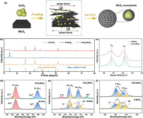
The XRD pattern of SnO2/MoS2 (Figure 1b) presents the distinctive peaks of SnO2 (JCPDS No. 41-1445) and MoS2 (JCPDS No. 37-1492). In comparison to B-MoS2, the SnO2/MoS2 demonstrates a weak and broad peak at (002)MoS2, which is shifted from 14.4° to 12.4°. This suggests that the exfoliated MoS2 layers have undergone expansion from 0.61 to 0.71 nm during the P-milling process.[32-35] Similarly, the Raman spectrum of SnO2/MoS2 (Figure 1c) reveals that the E2g and A1g bands of MoS2 shift to lower wavenumbers, and the difference between them decreases. This also implies the exfoliation and interlayer expansion of MoS2 after P-milling.[33, 36] The content of MoS2 in the composite can be calculated to be 47 wt% according to the TG results (Figure S3, Supporting Information).
The XPS characterization was employed to evaluate the chemical state of SnO2/MoS2. For the Sn 3d spectrum (Figure 1d), two prominent peaks observed at 495.5 and 487.1 eV correspond to the Sn 3d3/2 and Sn 3d5/2 peaks of Sn4+, respectively.[37] Moving to the Mo 3d spectrum (Figure 1e), a couple of peaks positioned at 229.4 and 232.9 eV are indicative of the 1 T phase of MoS2, while another pair at 230.1 and 233.5 eV are characteristic of the 2H phase of MoS2.[38] Based on the analysis of the peak areas, the SnO2/MoS2 composite exhibits a higher fraction of 1 T-MoS2 (75.1%) compared to B-MoS2 (28.2%), implying that SnO2 prevents the restacking of exfoliated MoS2 nanosheets. Additionally, the peak located at 226.5 eV is due to the S 2 s, and the peak at 236.3 eV represents the Mo6+ of MoO3, which may indicate slight oxidation by SnO2.[28] This observation is further supported by the presence of additional Sn2+ peaks in the Sn 3d spectrum of SnO2/MoS2. The S 2p spectrum (Figure 1f) is divided into two distinct sets of doublet peaks, where the peaks located at 162.3/163.4 and 162.9/164.1 eV can be assigned to the 1 T and 2H phases of MoS2, respectively.[39]
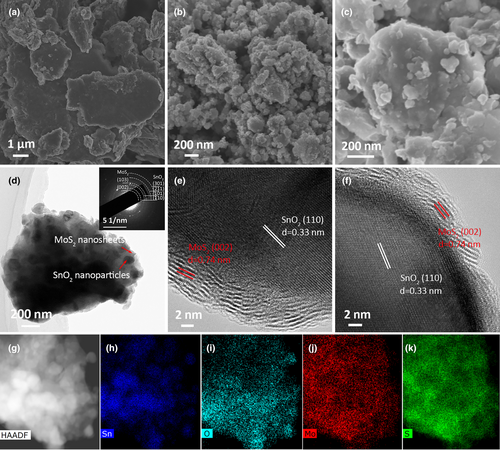
The microstructure of SnO2/MoS2 was thoroughly examined using SEM and TEM techniques. In contrast to the dense bulks of B-MoS2 (Figure 2a) and the loosely packed nanoparticles of B-SnO2 (Figure 2b), the SnO2/MoS2 exhibits a unique microgranular structure consisting of stacked nanoparticles (Figure 2c,d,g). The SAED pattern (inset of Figure 2d) confirms the presence of SnO2 and MoS2 within the microgranule. Element mapping of SnO2/MoS2 (Figure 2h–k) reveals that Mo and S are dispersed throughout the microgranuel, whereas Sn appears as concentrated dots, indicating SnO2 nanoparticles are embedded within the MoS2 matrix. In the HRTEM images of SnO2/MoS2 (Figure 2e,f), the wrapping of few-layered MoS2 around the SnO2 nanoparticles is clearly visible. The lattice fringe with interplanar spacing of 0.33 nm corresponds to the (110) plane of SnO2. At the edge of the SnO2 nanoparticle, distinct few-layered MoS2 wrapping (5–10 layers) with spacing of 0.74 nm can be observed, which is in accord with above XRD analysis.
To evaluate the performance of SnO2/MoS2 anode for Li+ storage, coin-type half-cells were assembled. The CV profiles of SnO2/MoS2 (Figure 3a) reveal the combined lithiation/delithiation processes involving both MoS2 and SnO2. In the initial cathodic scan, the peaks observed at 1.25 and 0.45 V are attributed to the intercalation of Li+ and subsequent conversion reaction of MoS2 to Mo, respectively.[37, 50] Furthermore, the peak at 1.05 V is assigned to the conversion of SnO2 to Sn, and the peaks at 0.76 and 0.18 V correspond to the alloying of Sn to LixSn.[20, 40] During the anodic scan, the peaks at 0.08 and 0.51 V are related to the dealloying reaction of LixSn to Sn. The broad peaks observed between 1.0 and 2.0 V are indicative of the reconversion reactions through which MoS2 and SnO2 are restored. However, it is important to note that only a portion of Li2S is able to react with Mo, while the rest is decomposed into S and Li+. This is reflected in the anodic peak at 2.25 V.[27, 51, 52] As a result, starting from the second cycle, a new cathodic peak at 2.0 V occurs, which results from the lithiation of S. The ascription of cathode/anode peaks of SnO2/MoS2 has also been affirmed by the CV tests of bare SnO2 and MoS2 (Figure S4, Supporting Information).
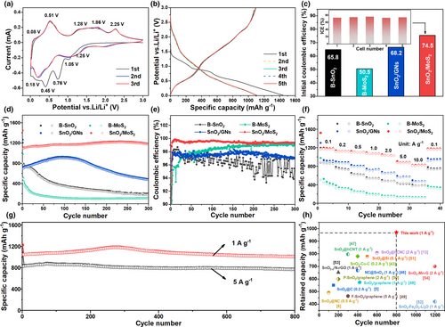
In the galvanostatic discharge/charge tests, the SnO2/MoS2 demonstrates an initial reversible capacity of 1091.1 mAh g−1 at 0.2 A g−1 (Figure 3b). This reversible capacity is closely aligned with the theoretical capacity of 1105.1 mAh g−1, which is calculated based on the weight percentages of SnO2 (53 wt%) and MoS2 (47 wt%). Furthermore, the average initial coulombic efficiency (ICE) of five different cells using SnO2/MoS2 as the anode is 74.5% (Figure 3c). This confirms the superior reversibility of Li+ storage compared to B-SnO2, B-MoS2, and SnO2/GNs (Figure S5, Supporting Information). The capacity remains stable throughout the subsequent cycles (Figure 3d), with the coulombic efficiency increasing to 99.2%–99.9% (Figure 3e). In contrast, the B-SnO2, B-MoS2, and SnO2/GNs suffer serious capacity decay and low CE during cycling. Furthermore, the SnO2/MoS2 exhibits higher rate capability than the B-SnO2, B-MoS2, and SnO2/GNs (Figure 3f). The average reversible capacity of SnO2/MoS2 only slightly decreases from 1160.5 to 1030.6 mAh g−1 as the rate increases from 0.1 C to 2 C (1 C = 1 A g−1). Even at a rate of 10 C, a reversible capacity of 815.8 mAh g−1 is maintained. When the rate returns to 0.1 C, the capacity rebounds to 1151.8 mAh g−1. Moreover, the SnO2/MoS2 exhibits superb long-term cyclic stability (Figure 3g). At 1 C, it demonstrates a reversible capacity of 1044.5 mAh g−1 in the initial cycle and maintains 1005.3 mAh g−1 after 800 cycles, resulting in a capacity retention of 96.2%. At a higher rate of 5 C, the reversible capacity reaches up to 825.8 mAh g−1 and retains 93.1% after 800 cycles. Obviously, the high-rate cycling performance of SnO2/MoS2 anode surpasses most reported SnO2-based anodes (Figure 3h). This highlights the superiority of combining MoS2 and SnO2 in the composite structure. To discuss the influence of the contents of SnO2 and MoS2 on the performance of composites, we have also prepared composites with MoS2 additions of 30, 50, and 70 wt% (Figure S6, Supporting Information). As shown in Figure S7, Supporting Information, the SnO2/MoS2 composite with MoS2 addition of 50 wt% exhibits much superior performance than those prepared with MoS2 additions of 30 and 70 wt%, considering the cycling performance and rate performance.
During the P-milling process, the exfoliation of bulky MoS2 leads to the formation of metallic 1 T-MoS2, which wraps the refined SnO2 nanoparticles and facilitates efficient charge/ion transfer. Thus, the electrical conductivity and ion diffusion of SnO2/MoS2 are greatly enhanced compared to those of SnO2 or MoS2 alone (Figure S8, Table S1, Supporting Information), which can be directly responsible for the improved rate capability. Moreover, the CV measurements at various scan rates were conducted to investigate the capacitive behavior behind the superior rate capability of SnO2/MoS2 (Figure S9a–c, Supporting Information). The current at a given potential can be composed of diffusion-controlled and capacitive currents. Figure S9d, Supporting Information, summarizes the capacitive contributions at various rates, rising form 70.4% (0.2 mV s−1) to 86.5% (1.5 mV s−1), which are higher than those of bare SnO2 and MoS2. The superior capacitive storage of SnO2/MoS2 results from the effective exfoliation of MoS2 sheets and refining of SnO2 particles. Additionally, the wrapping of MoS2 provides spatial confinement, mitigating the volume change experienced by SnO2 and contributing to enhanced cyclic performance. Despite the enhanced conductivity achieved through GNs wrapping, the SnO2/GNs composite exhibits inferior capacity due to the lower capacity of GNs when compared to MoS2.
To examine the evolution of capacity in SnO2/MoS2, the reversible capacity contribution is divided into three parts (Figure 4c), based on the charge profile and differential capacity (dQ/dV) plot (Figure 4a,b). Specifically, the capacity delivered in the range of 0.01–1.0 V represents the dealloying process of LixSn. The capacity delivered in the range of 1.0–2.0 V stems from the reconversion reaction of Sn and Mo, represented by Sn + 2Li2O → SnO2 + 4Li+ + 4e−, Mo + 2Li2S → MoS2 + 4Li+ + 4e−. Lastly, the capacity of 2.0–3.0 V originates from the delithiation of Li2S. Remarkably, the capacity deliveries of SnO2/MoS2 remain stable during cycling in the 0.01–2.0 V ranges, as observed by the well-maintained dQ/dV peaks even after 300 discharge/charge cycles. This suggests the superior reversibility of dealloying and reconversion reactions in the composite. Interestingly, within the 2.0–3.0 V range, the corresponding dQ/dV peak becomes more pronounced, and the capacity contribution increases by approximately 130 mA g−1 after 300 cycles, which closely aligns with the increase in total capacity. In contrast, the dQ/dV curves of B-MoS2 exhibit almost no peak after cycling, implying that the combination with SnO2 mitigates the dissolution of Li2S during long-term cycling. Conversely, B-SnO2 and SnO2/GNs demonstrate weakened dQ/dV peaks and reduced capacity delivery during cycling in the 0.01–2.0 V region (Figures S10, S11, Supporting Information). These observations can be attributed to the gradually irreversible nature of dealloying and reconversion reactions in these materials.
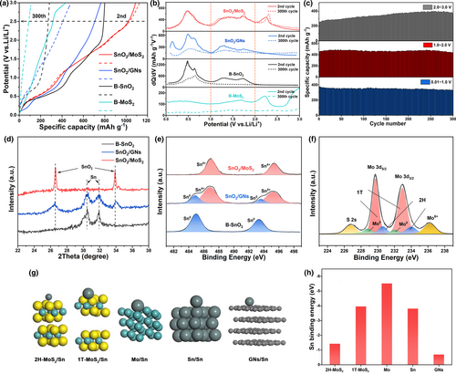
On the XRD pattern of B-SnO2 electrode tested at 0.2 A g−1 for 300 cycles, only diffraction peaks corresponding to Sn can be observed (Figure 4d). Similarly, only peaks corresponding to Sn0 can be detected on the corresponding Sn 3d XPS spectrum (Figure 4e). The XRD and XPS results indicate the SnO2 phase cannot be recovered, possibly because the coarsening of conversion product Sn inhibits the reconversion reaction.[53] In comparison, SnO2 can be partially recovered in SnO2/GNs after cycling, indicating the spatial confinement of GNs wrapping partially alleviates the Sn coarsening. However, for the electrode of SnO2/MoS2, SnO2 can be fully recovered without any residue of Sn even after extended cycling, indicating complete reconversion of Sn with Li2O. Figure 4f shows the Mo 3d XPS of cycled SnO2/MoS2 electrode, confirming the recovery of MoS2 after cycling. The comparisons indicate the combination with MoS2 is more effective than using GNs to enhance the reconversion of Sn with Li2O. During the discharge process, the conversion of MoS2 with Li+ gives rise to the Mo cluster, which can interact with Sn and impede its growing. DFT calculations (Figure 4g,h) were conducted to evaluate the affinities of Sn with 1 T-MoS2, 2H-MoS2, GNs, Sn cluster, and Mo cluster. The binding energy of Sn with GNs is −0.7 eV, which is lower than the binding energy of Sn with Sn clusters (−3.8 eV). This result suggests that the aggregation of Sn is more favorable than its adsorption on GNs in the SnO2/GNs system. In contrast, the binding energy of Sn with Mo clusters (−5.5 eV) is higher than the binding energy of Sn with Sn clusters, implying that Sn is preferentially adsorbed on the surface of Mo clusters. The spatial confinement, together with strong interaction, enables the good dispersion of Sn nanograins, which not only promotes the efficiencies of dealloying and reconversion reactions, but also enhances the structural stability of electrode. In contrast to severe cracking observed on the SnO2 and SnO2/GNs electrodes after cycling, the SnO2/MoS2 electrode remains intact without any cracks (Figure S12, Supporting Information).
Encouraged by the outstanding half-cell performance, we further investigated its efficacy when coupled with LiFePO4 in full-cells. The LiFePO4 cathode (Shenzhen Kejing Zhida Technology Co., Ltd) exhibits a high initial reversible capacity of 148.5 mAh g−1, with almost no capacity fading after 150 cycles (Figure S13, Supporting Information). The cathode-to-anode capacity ratio is 1.1:1, and the mass loading of cathode is 5.0–6.0 mg cm−2. Figure 5a illustrates the discharge/charge profiles of full-cells tested at 0.2 A g−1 and between 0.6 and 3.6 V. These full-cells exhibit noteworthy charge/discharge capacities of 1177.8/860.8 mAh g−1. Moreover, as shown in Figure 5b, they demonstrate remarkable cycling performance, retaining a high charge capacity of 590.5 mAh g−1 after 100 cycles. Even when cycled at 1.0 A g−1 for 100 loops, they still maintain a significant charge capacity of 469.8 mAh g−1. The outstanding performance of these full-cells can be comparable to those of reported SnO2-based full-cells (Table S2, Supporting Information), indicating the great potential of SnO2/MoS2 anode for practical applications.
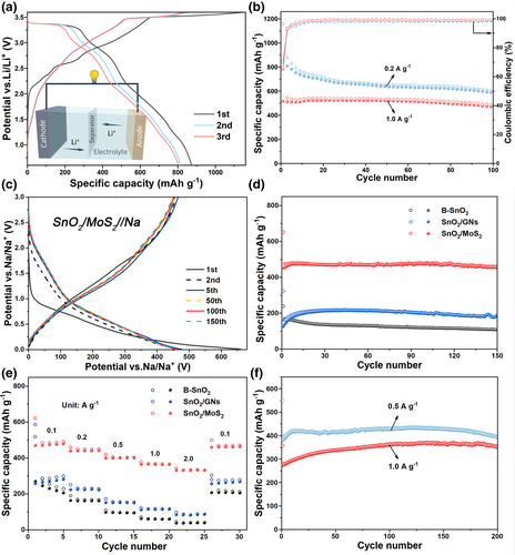
Additionally, the SnO2/MoS2 heterostructure also exhibits excellent performance for Na+ storage. The corresponding Na-storage process of the SnO2/MoS2 was revealed by the CV analysis and discussed in Figure S14, Supporting Information. In the galvanostatic discharge/charge test, it delivers a reversible capacity of 465.8 mAh g−1 at 0.2 A g−1, with an ICE of 70.6% (Figure 5c). Subsequent cycles show overlapping discharge/charge curves, showing a high capacity retention of 97.5% after 150 cycles. Although the SnO2/GNs also exhibits improved cyclic stability compared to B-SnO2, the capacity is only around 200 mAh g−1, much inferior to that of SnO2/MoS2 (Figure 5d). Moreover, the SnO2/MoS2 demonstrates a higher rate capability than the B-SnO2 and SnO2/GNs. It achieves average reversible capacities of 470.5, 441.2, 400.6, 365.8, and 332.2 mAh g−1 at 0.1, 0.2, 0.5, 1.0, and 2.0 A g−1, respectively (Figure 5e). Even cycled at 0.5/1.0 A g−1, the SnO2/MoS2 still retains high reversible capacities of 391.2/330.6 mAh g−1 after 200 cycles without any capacity degradation (Figure 5f).
3 Conclusion
In summary, the SnO2/MoS2 heterostructure was successfully fabricated via a facile one-step P-milling method, resulting in strong binding between SnO2 nanoparticles and MoS2 nanosheets. The MoS2 nanosheets with high fraction of 1 T phase provide spatial confinement to buffer the volume change of SnO2 and prevent coarsening of Sn during charge/discharge processes. Furthermore, as confirmed by various ex-situ characterizations and DFT calculations, the strong chemical interaction between Mo clusters and Sn clusters can effectively prevent Sn nanograins from aggregating and ensures the reversibility of Sn to SnO2, thereby significantly improving the Li+/Na+ storage. Consequently, the SnO2/MoS2 heterostructure exhibited high capacity, high rate, and long life in both LIBs and SIBs. The simplicity of strategy and scalability of fabrication method, combined with the outstanding performance, manifest the potential of the SnO2/MoS2 heterostructure for battery applications. Moreover, this viable strategy can be extended to other anode materials for high-performance LIBs.
4 Experimental Section
Material preparation
To obtain the SnO2/MoS2 composite, a mixture of SnO2 powder (99.9% purity, ~50 nm, Aladdin) and MoS2 (99.5% purity, 200 mesh, Aladdin) powder with a weight ratio of 1:1 underwent P-milled (Plasma-BM-L) for 15 h under pure Ar atmosphere. As a comparison, SnO2 and MoS2 powders were separately P-milled under the same condition to obtain bare SnO2 and MoS2 (B-SnO2 and B-MoS2), respectively. To emphasize the benefit of MoS2, the SnO2/graphene nanosheets (SnO2/GNs) was fabricated by P-milling a mixture of SnO2 and expanded graphite (EG) (1:1, w/w) for 15 h. The preparation of EG has been reported in our previous papers.[54, 55] The phase characterization and morphology observation of SnO2/GNs were discussed in Figures S1 and S2, Supporting Information.
Material characterization
The phase constitutions of samples were characterized by X-ray diffraction analysis (XRD, Panalytical Empyrean) and Raman analysis (Horiba HR Evolution). The component contents of samples were tested using thermogravimetric analysis (TG, Mettler-Toledo TGA2). The valance states of samples were recorded by X-ray photoelectron spectrometry (XPS, Thermo Fisher Escalab 250Xi). The morphologies of samples were examined using scanning electron microscopy (SEM, Carl Zeiss Supra 40) and transmission electron microscopy (TEM, JEOL JEM-2100).
Electrochemical measurement
The electrodes were composed of active material, binder (carboxymethyl cellulose), and conductive agent (Super P) with a weight ratio of 8:1:1. The Li+ storage performance was assessed by assembling CR2016 coin cells in a glove box with pure Ar environment. These cells employed Li foil as counter electrode, polyethene membrane as separator, and 1 M LiPF6 dissolved in ethylene carbonate/diethyl carbonate (1:2, v/v) with 5 wt% fluoroethylene carbonate (FEC) as electrolyte. The SIBs half cells were assembled using Na foil as counter electrode, glass fiber as separator, and 1 M NaClO4 dissolved in ethylene carbonate/propylene carbonate (1:1, v/v) with 5 wt% FEC as electrolyte. Battery testing equipments (LAND, CT3001A) were used to perform galvanostatic discharge/charge tests. Electrochemical working stations (Gamry Interface 1000) were utilized to obtain cyclic voltammogram (CV) profiles and Nyquist plots. The mass loading of the active material for electrochemical tests was 1.2–1.3 mg cm−2. Ex-situ XRD, XPS, and SEM observations were performed to reveal the stable structure of SnO2/MoS2 electrode. The cells were firstly discharged/charged, and then disassembled in the glove box, rinsed with PC for three times and dried in the glove box. For the ex-situ SEM, the dried electrode were taken out and immediately subjected to observation. For the ex-situ XRD, the electrodes were covered by Kapton film and were tested. For the ex-situ XPS, the electrodes were scraped off the Cu substrate and put inside the container filled with Ar atmosphere for analysis.
Acknowledgments
We acknowledge the financial support from the National Key Research and Development Program of China (2018YFA0209402, 2022YFB2502003), Guangdong Basic and Applied Basic Research Foundation (2023B1515040011), and Jiangxi Provincial Natural Science Foundation (20212BAB214028).
Conflict of Interest
The authors declare no conflict of interest.


