Artificial Hybrid Solid Electrolyte-Mediated Ca Metal for Ultradurable Room Temperature 5 V Calcium Batteries
Abstract
The anodic stability and reversibility of Ca metal electrodeposition/dissolution have always been hampered by surface passivation and anion corrosion, especially in F-based carbonate ester electrolytes at high device voltages. To avoid direct Ca metal/electrolyte reactions, an artificial hybrid solid electrolyte layer (AHSEL), which is characteristic of sodium/calcium carbonate and calcium hydride nitride nanocrystals of size <10 nm encapsulated by amorphous C, N species, is constructed on calcium with good ion conductivity (≈0.01 mS cm−1) and uniform coating of thickness ≈20 μm. After cycling in the KPF6 electrolyte, AHSEL is transformed into Na/K/Ca hybrid solid electrolyte interphases (SEIs), which is a compact layer composed of monodisperse nanocrystals (mostly Ca2NH) and small amorphous zones, thus greatly suppressing the fluoridation of the Ca deposit. Consequently, the plating/stripping performance of AHSEL-modified Ca (AHSEL-Ca) is markedly improved compared with that of pristine Ca, lasting for >1400 h at a polarization shift of <0.4 mV/h. The AHSEL-Ca anode also endows Ca batteries with superior anodic stability with a ceiling voltage of up to 5.0 V, a high discharge voltage (>3.3 V), a large capacity of ≈80 mAh g−1 at 200 mA g−1, and an ultralong lifespan ≈5000 cycles.
1 Introduction
Recently, Ca and Mg batteries have become increasingly attractive for meeting the ever-increasing demand for cost-effective and high-density energy storage, due to their similar ion radius and electropositivity, doubled charge transfer, lower cost, richer crustal reserve, and greater environment compatibility compared with Li and Na.[1-6] Previously reported Mg battery chemistry was quite successful with corrosive ether-based electrolytes and soluble interphases that avoided blocking in magnesium ion transport, although anodic stability issues remained for high-voltage battery configurations.[6-8] Similar Ca-like battery systems, however, cannot work in the absence of counterpart Ca salts. Meanwhile, SEIs, as a natural electrode–electrolyte separating layer beneficial to the stability of lithium ion batteries (LIBs), have been substantiated to passivate Ca severely due to the formation of an ion-/electron-insulative layer, thus inhibiting Ca2+ diffusion and leading to impractical Ca plating in various electrolytes.[9, 10] Owing to contributions from Ponrouch, Wang, Li, and Shyamsunder et al., feasible Ca plating–stripping was realized in both ether/ester electrolytes with calcium borates, borohydrides, and derivatives,[11-14] thus promoting subsequent research on screening suitable Ca2+ host materials and broadening electrolyte formulations.[15, 16] However, the anodic stability of Ca metal at high device voltages still falls far behind that of LIBs, and issues of continuing anion corrosion and severe polarization of calcium anodes remain unavoidable. Hence, developing a feasible strategy for Ca metal anodes with good anodic stability for high-voltage Ca batteries is necessary.
Some intrinsic SEIs evolved from metal anodes and carbonate ester electrolytes are known to exhibit good anodic stability with a high working voltage, even above 5 V, for LIBs and dual-ion batteries (DIBs).[17-19] However, protogenetic passivation layers for Ca and Mg usually affect the ion conductivity and plating/stripping reversibility adversely. Hence, spontaneous metal passivation and corrosion should be avoided by decoupling the metal–electrolyte interactions. For example, reversible Mg chemistry has been demonstrated to be feasible in carbonate ester electrolytes by fabricating Mg2+-permeable polymeric interphases.[2, 20] However, the voltages of the proof-of-concept Mg//V2O5 and Mg//PBA batteries remained below 3 V (PBA is Prussian blue analog). The first alkaline earth metal battery with a voltage higher than 4.0 V was achieved through a strategy of hybrid SEIs.[21] The Ca batteries stably ran 1900 cycles at 2.0–4.5 V with 83% capacity retention via in situ-evolved Na/Ca hybrid SEIs benefiting from fast Ca2+ transport. Similarly, Song et al.[22] used Li/Ca hybrid SEIs to obtain a Ca metal battery at 2.0–4.7 V with 77% capacity retention. The results of these studies imply that it is possible to tailor the reversibility of metal chemistry by selecting appropriate solid electrolyte interphases. This prompted us to develop an artificial solid electrolyte layer, avoiding metal–electrolyte direct reaction, to realize reversible chemistry and enhanced anodic stability of alkaline earth metal suitable for high device voltages (e.g., 5.0 V), which is currently unavailable and highly desirable.
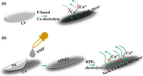
In this study, we demonstrate, for the first time, a facile method to construct an AHSEL-Ca electrode (AHSEL-Ca), suitable for an ultradurable 5 V Ca metal battery. Ca ion diffusion is forbidden for pure Ca SEIs evolved by pristine Ca in Ca(PF6)2 electrolyte (Scheme 1a), while it is free and fast for Na/K/Ca hybrid SEIs co-evolved with AHSEL-Ca and KPF6 electrolyte (Scheme 1b). This is because pure Ca SEIs of mainly ion/electron-insulative CaF2 were substituted by Ca2NH-rich Na/K/Ca hybrid SEIs with good Ca ion permeability due to out-of-control fluoridation in Ca(PF6)2 or Ca(BF4)2 ether and ester electrolytes.[23] Meanwhile, deep anion penetration was largely inhibited, indicating that fresh Ca deposits were fully protected from corrosion and passivation. Therefore, Ca plating/stripping with little polarization shift and weakened overpotentials could readily last for more than 1400 h. The corresponding Ca batteries also exhibited excellent anodic stability up to 5.0 V for a very durable life span of nearly 5000 cycles. The crucial K/Ca/Na hybrid SEIs are inseparable from the pre-engineered interface of AHSEL, which was evolved through interactions of N-methyl pyrrolidone (NMP) sandwiched between sodium and calcium plates.
2 Results and Discussion
2.1 Artificial Hybrid Solid Electrolyte Layer
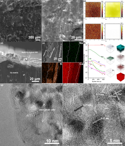
The surface solid electrolyte at Ca, that is, AHSEL, was prepared by a solid–liquid–solid-guided reaction between Na, Ca, and NMP. SEM characterization proved that the surface topology of the pristine Ca plate (Figure S1) was modulated after the formation of AHSEL (Figure 1a). Large up-and-down fluctuations are replaced by a uniform roughness configuration of the solid electrolyte, appearing as extra details of the coating layer (Figure 1a,b). TOF-SIMS 2D mapping analysis of C+, N+, Na+, and Ca+ modes (Figure 1c) indicated the uniform existence of C, N, and Na elements in the surface coating. A distinct delaminated microstructure can be observed in the low-magnification cross-sectional SEM image of AHSEL-Ca (Figure 1d), indicating possible different compositions between AHSEL and the matrix Ca layer. The EDS element mapping depth profile (Figure 1e) of the high-magnification cross-sectional SEM image further shows the gradient distribution of Na and Ca across the layer microstructure. The quantitative line-scan EDS of the sample scraped from the surface of AHSEL-Ca was performed using high-angle annular dark-field scanning transmission microscopy (HAADF-STEM; Figure S2a,b), verifying the existence of these elements in AHSEL. The sudden increase in intensity of the Ca peak at 180 nm in the line-scan EDS is probably due to exfoliated Ca from the matrix. Moreover, the higher carbon content in the outer surface indicates that the organic carbon encapsulates the inorganic phase configuration of the AHSEL. TOF-SIMS depth profiling and 3D mapping analysis (Figure 1f) showed the C-, N-, Na-, and Ca-containing AHSEL surface and their gradient distribution configurations.
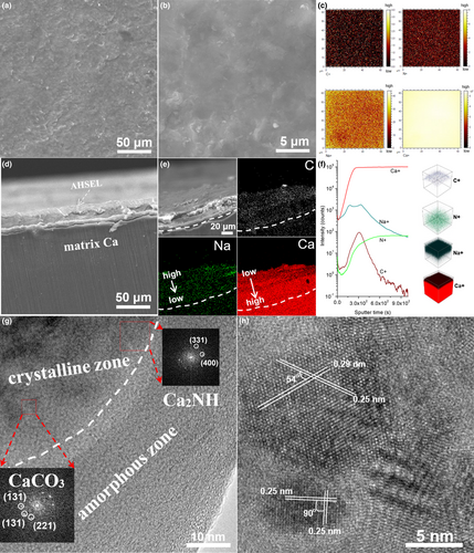
In addition to the major phase of cubic Ca (PDF No. 23-0430) from matrix Ca, the crystalline phases in the as-prepared AHSEL-Ca contain the common carbonates of sodium and calcium, that is, orthorhombic CaCO3 (PDF No. 17-0763) and monoclinic Na2CO3 (PDF No. 19-1130), as well as an unusual Ca compound, that is, cubic Ca2NH (PDF No. 71-0051), which were all verified by XRD (Figure S3a) characterization. Moreover, a wide amorphous package is also discernable at 2θ ≈ 26°, which is quite different from the XRD pattern for pristine Ca. Surface elemental analysis by XPS (Figure S3b) confirmed the presence of C, N, O, Na, and Ca in the outmost thin layer. Chemical bonding of C=O from carbonates (Na2CO3 and CaCO3) at 289.2 eV and Ca–NH from Ca2NH at 346.3 and 349.8 eV was also substantiated in the deconvoluted C 1s, N 1s, Na 1s, and Ca 2p XPS spectra (Figure S3c), which is well consistent with the XRD results, except for the extra bonding of C–C (284.6 eV), C–N (285.3 eV), and –C=O (288.3 eV), indicating the presence of organic carbon in the AHSEL.[24, 25] Interestingly, although a high sodium content was confirmed at the interface by the EDS (Figure S3d,e) spectra, no N element was detectable, implying that the phase of Ca2NH may be deeply embedded in organic carbon, which contains a very small amount of N according to the TOF-SIMS depth profiling analysis. HRTEM images (Figure 1g,h) of the sample scraped from AHSEL show that crystalline particles were fully encapsulated by the amorphous phase, possibly organic carbon, consistent with the results of XPS and TOF-SIMS analyses.
Nanocrystals smaller than 10 nm display well-defined lattice fringes, of which the diffraction pattern by fast Fourier transform (FFT), lattice spacings, and angles of crystal planes are consistent with those of sodium/calcium carbonates and Ca2NH, as observed in the XRD pattern. Obviously, we have realized the protection of Ca by the surface AHSEL, which can avoid the direct Ca electrolyte reaction. In addition to a full protection, good ion conductivity is essential for AHSEL-Ca to be effective in Ca metal batteries. The electrochemical impedance spectrum (EIS) of an all-solid Ca//AHSEL-Ca cell showed that the artificial solid electrolyte exhibits a good ion conductivity of 0.01 mS cm−1 (Figure S4).
2.2 AHSEL-Ca Symmetric Batteries
The Ca plating–stripping performance was tested in symmetric batteries to verify the protection efficiency of the AHSEL. Ca plating–stripping of pristine Ca in 1 m Ca(PF6)2 or Ca(BF4)2 EC/DEC (1:1, v/v) electrolyte exhibited very poor stability due to severe anion corrosion and polarization.[21, 22] At current densities of 0.025 and 0.1 mA cm−2, the Ca//Ca symmetric batteries can only last for less than 52 and 12 h, respectively. After that, the deposition potentials quickly shift to −5.0 V due to the extremely large internal resistance from mass formation of thick CaF2 insulative layer.[21, 26] In contrast, the plating–stripping of pristine Ca in a 1 m KPF6 EC/DMC/EMC (1:1:1, v/v/v) electrolyte can be prolonged to more than 800 and 250 h under the same test conditions (Figure 2). This result is comparable to pristine Ca in the NaPF6 electrolyte,[21] because similar K/Ca hybrid SEIs characteristics of KCa(PO3)3 (PDF No. 39-1408), Ca(H2PO4)2 (PDF No.70-1381), and CaF2 (PDF No.77-2093) nanocrystals smaller than 20 nm evolved above the Ca deposition layer, which, to some extent, alleviated anion corrosion and hindered out-of-control fluoridation, as revealed by the SEM, XRD, EDS, TOF-SIMS, and HRTEM characterization of the cycled Ca electrode (Figure S5). However, fluoridation of fresh Ca deposit occurred slowly, leading to failure of Ca//Ca batteries in 258 h with a capacity of 0.6 mAh cm−2 at 0.1 mA cm−2 (Figure 2b). The result also suggests that the microstructure of K/Ca hybrid SEIs is still not compact enough and may lack some organic carbon species (as revealed by TOF-SIMS; Figure S5e) to fully avoid mild etching and passivation of freshly formed Ca.
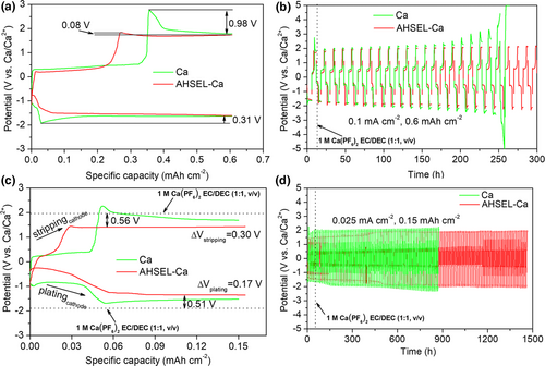
In contrast, polarization and anion corrosion were radically suppressed using AHSEL-Ca. At the current rate of 0.1 mA cm−2, the overpotentials for Ca deposition/dissolution have reduced by 0.31 and 0.90 V (from 0.31 to 0 V and from 0.98 to 0.08 V; Figure 2a). At 0.025 mA cm−2, the potential barrier for Ca deposition and dissolution was also slightly lowered by 0.17 and 0.30 V, respectively (Figure 2c). Although a steady Ca deposition potential of −1.35 V versus Ca/Ca2+ is still much more negative than in ether-based electrolytes or with precious metal current collectors owing to the pseudo-reference of Ca,[12, 13, 26] the result is still significant considering the use of cost-effective commercial Ca as the current collector. More importantly, the fluoridation of fresh Ca deposits fundamentally changes, enabling more than 1400 h stable plating–stripping cycles with a very small polarization shift of <0.4 mV/h at a capacity of 0.15 mAh cm−2 (Figure 2d).
The interface microstructure characterization reveals that the surface of the cycled AHSEL-Ca appears as a uniform and compact coating, confirmed as ternary Na/K/Ca hybrid SEIs, which cover the mixture deposition layer of K/Ca, and then the matrix Ca below (Figure 3a–f). The major crystalline phases in the hybrid SEIs were verified as Ca2NH from AHSEL and more from AHSEL–electrolyte interaction, while minor phases of hexagonal KCa(PO3)3, orthorhombic Na3(PO3)3·H2O (PDF No. 15-0740), and cubic KCaF3 (PDF No.03-0567) were also observed in the XRD pattern (Figure S6a). The uniform distribution of N, Na, and K elements revealed by the 2D TOF-SIMS N+, Na+, K+, and Ca+ analyses, and their uniform distribution in the EDS mapping of the corresponding cross-sectional SEM and HAADF-STEM images (Figures S6b and S7, and Figure 3c–e) of the hybrid SEIs, demonstrates that the gradient distribution of Ca/Na elements in the pre-engineered interface of AHSEL has suffered considerable rearrangement through the interaction with the K-based electrolyte. Thus, the well-defined amorphous layer in AHSEL disappears. Instead, small amorphous zones remain interspersed among the gaps of nanocrystals, preventing their further growth, which accounts for the non-coarsening crystals of <10 nm, similar to that in the AHSEL (Figure S8 and Figure 3g). The HRTEM image (Figure 3h) shows that Ca2NH nanocrystals have well-defined lattice fringes with plane spacings of 0.25 and 0.29 nm, consistent with the interplanar spacings of (222) and (400) reflections in the XRD pattern. The Ca2NH-rich inorganic–organic Na/K/Ca hybrid SEIs were also confirmed by the surface N-/C-rich element distribution displayed by the TOF-SIMS depth profiling and 3D mapping analysis (Figure 3f), which is quite different from AHSEL with amorphous layer encapsulation N-rich Ca2NH and that of K/Ca SEIs with few organic species. The C–N and C=N stretching vibrations, and the C–H stretching vibration of N–CH3 moiety, are characterized by distinct absorbance peaks at 1026–1306, 1650, and 2855 cm−1 in the FT-IR spectra (Figure S9) of the Na/K/Ca hybrid SEIs and precursor AHSEL, which both substantiate their unique organic species, quite different from that of K/Ca hybrid SEIs.[24] XPS of the cycled AHSEL-Ca and after 120 s of plasma etching (Figure S10) also confirm the composition and variation of the SEIs, consistent with the above analysis. CN species and Ca2NH nanocrystals in hybrid SEIs have at least two benefits. One is the enhancement of the charge-transfer conductivity for the SEIs (Figure S11), and the other is the direct inhibition of CaF2 formation, as clearly revealed by the XRD patterns (Figures S5b and S6a), in sharp contrast to K/Ca or Na/Ca SEIs with CaF2 surviving as the major component of the interphases.[21, 22] Overall, the compact packing of crystalline–amorphous hybrid SEIs, especially the introduction of Ca2NH nanocrystals, guarantees a selective rapid permeability of Ca2+, rather than , and thus fundamentally solves the problems of passivation and corrosion of Ca metal by forming CaF2.
2.3 High-Voltage and Ultradurable AHSEL-Ca Batteries
FGCFM was chosen as the cathode for full Ca metal batteries and AHSEL-Ca as the anode. The membrane electrode, which has good ion/electron conductivity, can avoid the adverse effects of the binder, and simultaneously afford many active sites for energy storage, benefiting from the few-layered graphitic nanostructure, many heteroatom-doping defects, and a large surface and porous structure, as revealed by the SEM, TEM, EDX, XRD, XPS, and N2 adsorption–desorption characterization (Figures S12 and S13).[27-29] To test the safe reliability and anodic stability of AHSEL-Ca under deep plating–stripping conditions, a high window voltage of 2.0–5.0 V is preset. The Ca battery delivers an initial discharge capacity of ≈86 mAh g−1 at 200 mA g−1, and a high capacity of ≈79 mAh g−1 can be retained after 50 cycles, with the average discharge voltages ranging from 3.32 to 3.47 V (Figure 4a). The voltage profiles are characteristics of two plateaus at about 3.8–4.9 V and 2.0–2.9 V, with a steep slope between them. The two plateaus correspond to the cathodic peaks at 2.41 and 4.40 V in the differential capacity curves (inset view of Figure 4a), similar to those of previous Ca metal batteries,[21] to be discussed in the following section. After 200 cycles (Figure 4b), a capacity of ≈60 mAh g−1 was retained, which is equivalent to a superior capacity retention of ≈70%. To facilitate comparison, a cycle with a coulombic efficiency of 90% was chosen for the rate analysis. At various rates ranging from 200 mA g−1 to 1 A g−1 (Figure 4c), the average discharge voltage holds around high voltage of 3.13–3.30 V. In the meantime, ≈66% of the reversible capacity at 200 mA g−1 can be output at 1 A g−1 (50 mAh g−1 vs 76 mAh g−1). The Ragone plots (Figure 4d) show that an impressive energy density of ≈250 Wh kg−1 can be achieved at a power density of 657 W kg−1, while at a large power density of 3.19 kW kg−1, the Ca battery can still deliver a high energy density of ≈161 Wh kg−1, comparable to advanced dual-ion batteries, Al-ion batteries, and Ca metal batteries reported previously.[17, 21, 22, 30]
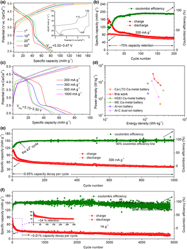
Except for good energy/power performance, Ca metal batteries also exhibit good long-term cycling stability. At 300 mA g−1, the Ca battery ran stably for 1000 cycles with a very small capacity decay of ≈0.05% per cycle. More impressively, the coulombic efficiencies are roughly above 95%, except for the initial aging cycles, needed to evolve a stable interphase for the cathode.[21, 22] Even at a very high current rate of 1 A g−1, the Ca battery can safely run for nearly 5000 cycles, with coulombic efficiencies being roughly larger than 90% for the initial 3000 cycles and slowly declining to above 80% subsequently. Notably, the capacity decay always holds at a very low level of ≈0.01%, except the initial aging cycles. Evidently, though Ca metal batteries were tested under high voltage up to 5 V, high rate, and long duration, it is verified that the AHSEL-Ca metal is suitable for safe and deep Ca plating–stripping battery operation conditions. This indirectly proves the feasibility of AHSEL in decoupling metal electrodes and liquid electrolytes, and points to a possible direction for realizing safe metal batteries with high energy density.
2.4 Electrochemical Energy Storage Mechanism
Because the charge-transfer mechanism for the anodes of all metal batteries follows the same equation as M ↔ Mn+ + ne−, Ca plating–stripping of AHSEL-Ca has also been investigated in symmetric batteries (Section 2.2). Hence, we mainly analyzed the mechanism of the cathode. The ex situ XRD patterns for the FGCFM cathode at various stages of charge–discharge (SOC) are presented in Figure 5a. During the first charge process from the open circuit voltage (OCV) to 5 V, the left shift of the (002) reflection and weakened intensity of the (101) reflection of the graphite-2H structure indicates that the insertion reaction of anions occurs in the graphitic carbon due to intercalation or adsorption reactions according to Bragg law (d(hkl) = nλ/2sinθ, where d(hkl) is the interplanar spacing of the (hkl) crystal plane, θ is the diffraction angle, and λ reflects the wavelength of the incident radiation, for example, X-ray or neutron), similar to those of dual-ion and anion-cation relay batteries.[17, 31] The discharge process features two plateaus, as mentioned above, the upper voltage corresponding to the extraction reaction of anions, which leads to the recovery of characteristic reflections for the graphite-2H structure, and the lower voltage one assignable to the insertion reaction of cations, K+ and Ca2+, as confirmed by the slight shift of the (002) reflection.
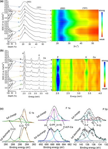
Considering the lack of an obvious shift, it is reasonably speculated that the cation insertion reaction mainly arises from chemical adsorption of defects, pores, and some surface/interface organic groups in the graphitic carbon.[32] This also accounts for almost no shift of the (002) reflection in the early charge stage before 4 V for the subsequent charge process, implying the desorption of the absorbed cations. When further charging to 5 V, an obvious shift of the (002) reflection to the left appears again as a result of the reinsertion of anions into the cathode. The reflection shift repeatedly recovers after a subsequent discharge to 3 V and then reappears because of cation adsorption for discharge to 2 V afterward. Interestingly, the relevant adsorption–desorption reaction of cations results in a very small reflection shift for (002), but leads to a significant weakening of the (101) reflections. These variations in the XRD profiles are clearly reflected in the corresponding contour color map. Overall, an anion–cation relay storage mechanism can be rationally deduced for the cathode (Cn + x ↔ Cn(PF6)x + xe−, Cn + yK+ + zCa2+ ↔ Cn(Ky/Caz) + (y + 2z)e−, where Cn represents the graphitic carbon). The variation of insertion–extraction species is also reflected in the EDS results. The normalized intensity of EDS spectra (Figure 5b) for cathode at various SOCs indicates a clear rule that peak intensity of K and Ca elements (relative content) is strengthened at the cation adsorption stage of 2.0 V, with weakened peak intensity for P, while peak intensity of P increases with decreasing peak intensity of K and Ca elements at anion-intercalated stage of 5.0 V, confirming the anion–cation relay storage mechanism. The contour color map vividly reflects the intensity variation of the normalized EDS spectra. The oxidation and reduction states of graphitic carbon in the relay insertion/extraction process can be analyzed using the deconvoluted C 1s, F 1s, and P 2p XPS spectra (Figure 5c). From reduction state to oxidation state, the doping O species, that is, C=O bonding at the lower energy state, is oxidized to C–O–PFn (n < 5) species, that is, C–O–P bonding at higher energy state, in the charge, as revealed by the weakening peak intensity of C=O bonding at 288.7 eV for C 1s, and new emerging P–F bonding at 687.4 eV and P–O bonding at 134.5 and 136.5 eV of spin split peaks of P 2p from the C–O–PFn species.[33]
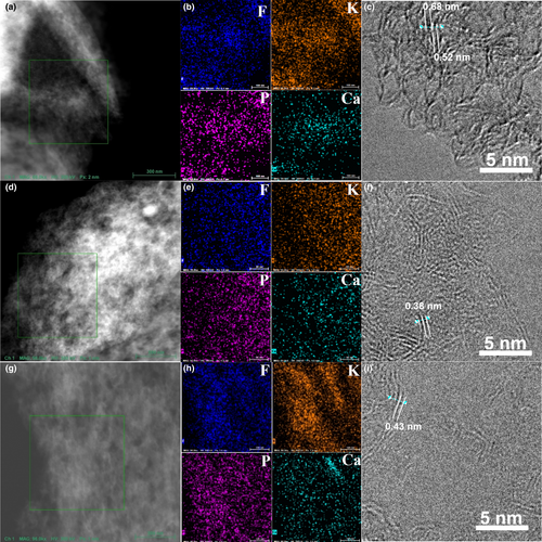
Furthermore, the EDS element mapping in HAADF-STEM mode and the HRTEM images for the cathodes at different discharge depths (Figure 6) indicate the same mechanism, in coincidence with the XRD and XPS results. At the discharge depth of 0, that is, anion-intercalated stage, element mapping and HRTEM images of the cathode (Figure 6a–c) are characteristics of very expanded lattice spacings of 0.52 nm, even 0.68 nm for graphitic layers, and finer color for P element due to inclusion and aggregation of ions. The lattice spacing recovered to about 0.38 nm after a discharge depth of 50%, indicating the extraction of anions (Figure 6d–f). As the discharge process progresses to 100% discharge depth, a slight increase in the graphitic lattice spacing to 0.42 nm is attributed to the insertion of K-/Ca-based cations due to adsorption or intercalation reactions, in addition to the brighter colors for the corresponding element mapping images (Figure 6g–i). A more reliable quantitative element analysis (Figures S14–S22) similarly indicates an anion–cation relay insertion–extraction mechanism accompanying a K+/Ca+ competitive adsorption process, implying that the total number of active adsorption sites for is constant. Almost equally divided parts of anion insertion/extraction and cation adsorption/desorption in the discharge depth profile also illustrate their nearly equivalent capacity contributions.
3 Conclusions
An AHSEL was constructed on calcium to decouple the direct interaction between the Ca metal and the electrolyte. Except for good Ca ion permeability, AHSEL also protects fresh Ca deposits, against CaF2 formation. Various characterization techniques confirmed that the enhancement of the plating/stripping reversibility and anodic stability of the AHSEL-Ca electrode is attributed to the formation of Ca2NH-rich inorganic–organic Na/K/Ca hybrid SEIs, which guarantees comprehensive protection against passivation and good charge-transfer conductivity. Due to the very facile procedure to fabricate the AHSEL and good Ca battery performance under harsh test conditions (5.0 V, high rate, long duration), our work fully substantiates that constructing AHSEL is very suitable for practical applications. Hence, in this direction, we believe that practical Ca metal batteries with anticipated high energy density will soon become true. Meanwhile, it may also be applicable for addressing other bottleneck issues that have long been faced by the battery community.
4 Experimental Section
Materials
Pristine Ca plates were prepared by pressing commercial Ca granules (99.9%; Sigma-Aldrich) to a thickness of approximately 100–150 μm. AHSEL-Ca was prepared by dropping 25 μL NMP (AR, Guanghua Reagent Company) onto the surface of a Ca plate, which was then covered with a larger Na plate (99.9%; Sigma-Aldrich). The Na and Ca plates were kept under close contact by glass slides and book clips, and AHSEL-Ca will be achieved by peeling the Na plate after a reaction duration of 1 h. Freestanding graphitic carbon fiber membrane (FGCFM) was synthesized by an ethylene glycol-assisted vacuum pyrolysis of delaminated cellulose paper at 1000 °C for 6 h in a tube furnace.[21] The temperature ramp rate was 10 °C min−1.
Physicochemical characterization
The microstructure, composition, and chemical bonding of Ca, AHSEL-Ca, and FGCFM electrodes were characterized by thermal field emission scanning electron microscopy (SEM, Quanta 400F, 20 kV), field emission transmission electron microscopy (TEM, FEI Tecnai G2 F30, 300 kV), energy-dispersive X-ray spectroscopy (EDS), X-ray photoelectron spectroscopy (XPS, ESCA Lab250, Al Kα radiation), and Fourier transform infrared (FT-IR) spectroscopy. Powder X-ray diffraction (XRD) analysis was conducted using a powder X-ray diffractometer (D/MAX 2200, Cu kα1, 5° min−1). N2 adsorption–desorption Brunauer–Emmett–Teller (BET) surface area and Barrett–Joyner–Halenda (BJH) pore distribution analyses were performed on a Micromeritics instrument (ASAP 2420) to evaluate the surface and pore properties of FGCFM. Time-of-flight secondary ion mass spectrometry (TOF-SIMS) was performed to obtain insights into the depth profiling of the variation of elements involved in the surface components of Ca electrodes. The organic species in AHSEL and SEIs were also analyzed by FT-IR and XPS after different plasma etching durations. Ex situ XRD, EDS, XPS, and TEM of FGCFM cathodes at different charge/discharge depths were performed for the mechanism analysis.
Electrochemical characterization
Ca//Ca, and AHSEL-Ca//AHSEL-Ca symmetric cells were assembled with a 1 m KPF6 ethylene carbonate (EC)/dimethyl carbonate (DMC)/ethyl methyl carbonate (EMC) (1:1:1, v/v/v) electrolyte, and a glass microfiber filter (Whatman) separator. FGCFM was tailored to an appropriate size and directly used as the cathode in full Ca metal batteries, with a weight of ≈0.30–0.75 mg cm−2. In an Ar-filled universal glove box with oxygen and water vapor pressure <0.3 ppm, standard cells (CR2032) with AHSEL-Ca and FGCFM electrodes, a glass microfiber filter separator, and 75 μL electrolyte were assembled.
The galvanostatic plating–stripping tests of symmetric batteries were tested at 0.025 and 0.10 mA cm−2 with capacities of 0.15 and 0.60 mAh cm−2, respectively. The full Ca batteries were tested at various galvanostatic current rates ranging from 200 mA g−1 to 1 A g−1, with a window voltage of 2.0–5.0 V. All the tests were performed on a multichannel Neware battery testing system. The ion conductivity of AHSEL was evaluated by electrochemical impedance spectroscopy (EIS) of an all-solid Ca//AHSEL-Ca battery at an alternating current (AC) signal amplitude of 5 mV and a frequency range of 5–100 kHz. EIS of other batteries was also tested to evaluate the charge-transfer kinetics for SEIs. Cells for mechanism analysis were discharged and charged to different cutoff voltages. All the electrodes were washed with DMC to eliminate the residual electrolyte.
Acknowledgements
We acknowledge the support from the National Natural Science Foundation of China (Nos. 51872339, 91963210, and U1801255). C.W. also thanks the Key Research and Development Program of Guangdong Province (No. 2020B0101690001). Xiaoqin Wen from Shiyanjia Lab (www.shiyanjia.com) is also appreciated for the TOF-SIMS test of the electrodes.
Conflict of Interest
The authors declare no conflict of interest.


