A numerical method for solution of incompressible Navier–Stokes equations in streamfunction-vorticity formulation
Funding information: Higher Education Commission, Pakistan, NRPU No. 7781; Pakistan Science Foundation, PSF No. 5651
Abstract
In this work, we have proposed a numerical approach for solving the incompressible Navier–Stokes equations in the streamfunction-vorticity formulation. The numerical scheme is based on the diagonally implicit fractional-step (DIFST) method used for the time discretization and the conforming finite element method for the spatial discretization. The accuracy and efficiency of the scheme are validated by solving some benchmark problems. The numerical simulations are carried out using the DUNE-PDELab open-source software package. The comparison of DIFST scheme with different time discretization schemes is provided in terms of CPU time. Also, different solvers with preconditioners are investigated for solving the resulting algebraic system of equations numerically.
1 INTRODUCTION
The numerical study of partial differential equations (PDEs) is central to a wide variety of applications in science, and engineering. They are employed to simulate the physical phenomena such as fluid flow, electrostatics, the propagation of heat or sound, elasticity, electrodynamics, and so forth. There is increasing interest in the numerical study of large-scale nonlinear PDEs, whose exact or approximate analytical solutions are difficult to calculate. Therefore, efficient and accurate numerical methods such as the finite element, the finite difference, the volume methods, and the spectral methods are some generally adopted numerical scheme for solving such equations. However, the finite difference methods give poor approximation between grid points while the finite element method use basis functions that are non-zero on small subdomains. Particularly, in computational fluid dynamics (CFD), the high-order finite element methods have gained greater attention in solving problems with complex geometries.1 The CFD methods are becoming an important alternative to experiments for solving several fundamental and practical problems in fluid dynamics.2 The incompressible Navier–Stokes equations (INSEs) are a system of PDEs that are fundamental in CFD.3, 4
There are many numerical schemes available for solving the INSEs numerically in primitive variables. However, most of the methods require solving the pressure or pressure-correction Poisson equation, which serves to satisfy the continuity equation.5 Although, there are many alternative6, 7 but the streamfunction-vorticity formulation has the advantage of eliminating the pressure as a solution variable with mass conserving properties.8, 9 This formulation has also been used for image inpainting problems.10
In this work, the conforming finite element method11, 12 is used for solving the coupled vorticity transport and Poisson's equation simultaneously.13, 14 The DUNE-PDELab is used for the numerical simulations.15-17 The PDELab is open-source software package for solving PDEs numerically and is based on Distributed and Unified Numerics Environment (DUNE).18
The structure of this article is as follows. In Section 2, the governing equations with appropriate initial and boundary conditions are given. Section 3 describes the variational formulation. Section 4 provides the resulting linear and nonlinear system of equation. Section 5 is based on the temporal discretization. In Section 6, numerical results and stability of the method are provided. The comparison of different solvers and preconditioner matrices are also given. Finally, Section 7 concludes this article.
2 PROBLEM STATEMENT
Here, (d = 1, 2, 3) is a bounded domain with boundary , is the streamfunction and is the vorticity. Further, the is the fluid velocity, is the kinematic viscosity, and f is external source term. The Dirichlet boundary conditions and are set for both components of coupled system on boundary . Similarly, and are initial conditions for both components, respectively.
3 WEAK FORMULATION
For the weak solution, the existence, uniqueness and consistency of solutions, that is, well-posedness in the Hadamard sense, is easier to prove.20 After the multiplication of Equation (1a) with the test function and Equation (1b) with the test function and using integration by parts, we arrive at the weak formulation:
Now, we identify the temporal and spatial residual forms from Equations (2) and (3) as follows;
The spaces and can differ as different types of boundary conditions can be incorporated into the ansatz spaces. In this work, both the spaces are constrained by the same Dirichlet boundary conditions.
4 ALGEBRAIC PROBLEM
We assumed that so that the Jacobian matrix is invertible. The Newton's method needs the solution of the linear system in each iteration. So, the resulting linear system can either be solved by direct or iterative linear solvers. In this work, different iterative solvers with various preconditioners are tested as given in Table 3.
5 TEMPORAL DISCRETIZATION
One of the simplest ODEs solver is the one-step- method23 that reads:
By rearranging the terms of Equation (11), leads to the solution of a nonlinear system with the same structure as before at each time-step.24
By rearranging the terms of Equation (11), leads to the solution of a nonlinear system with the same structure as before at each time-step.24
The residual form Equation (12) consists of a linear combination of spatial and of temporal residual forms.
The Runge–Kutta method:
The explicit schemes are characterized by for and for . The diagonally implicit schemes are characterized by for . Without loss of generality it can be assumed that . Moreover, some diagonally implicit schemes, implemented in this work satisfy .
- One step scheme:
For the explicit/implicit Euler scheme () and for the Crank–Nicolson scheme ().
- Heun's second-order explicit method
- Alexander's two-stage second-order strongly S-stable method27:
with .
- Fractional step scheme28:
three stage second order strongly A-stable scheme. With , , . Note also that .
With = , the damped Newton method is used to solve the nonlinear system, while we used different linear solvers with preconditioners to solve the resulting system of linear equations.
6 NUMERICAL RESULTS
In this section, the computed results for some test problems are provided.
6.1 Test problem 1:
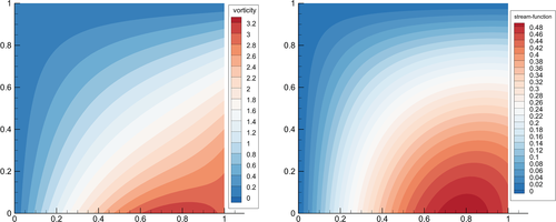
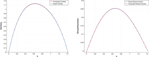
For the purpose of numerical simulation, we have chosen , , and . The computed results given in Tables 1 and 2 are obtained by using the combination of DIFST scheme, Newton's method and preconditioned SSOR BiCG-Stab for time discretization, nonlinear and linear solvers respectively. The computed solutions are shown in Figure 1A,B at time and . In Figure 2, plots over the line are shown for comparison of the computed and exact solutions and a very good agreement is observed.
| T | b = c | Linear ITs | Nonlinear ITs | error | CPU time (s) |
|---|---|---|---|---|---|
| 2.0 | 0.1 | 14905 | 14905 | 1.0712E-03 | 1.8352e+01 |
| 2.5 | 0.1 | 17963 | 17963 | 3.9923E-04 | 1.2694e+01 |
| 3.0 | 0.1 | 21035 | 21035 | 1.4879E-04 | 2.7985e+01 |
| 3.5 | 0.1 | 23873 | 23873 | 5.5456E-05 | 3.2656e+01 |
| 4.0 | 0.1 | 26845 | 26845 | 2.0668E-05 | 3.7321e+01 |
| 4.5 | 0.1 | 29843 | 29843 | 7.7027E-06 | 4.1962e+01 |
| 5.0 | 0.1 | 32871 | 32871 | 2.8712E-07 | 4.6629e+01 |
| T | b = c | Linear ITs | Nonlinear ITs | error | CPU time (s) |
|---|---|---|---|---|---|
| 2.0 | 0.1 | 14905 | 14905 | 2.1144E-02 | 1.8352e+01 |
| 2.5 | 0.1 | 17963 | 17963 | 7.8807E-03 | 1.2694e+01 |
| 3.0 | 0.1 | 21035 | 21035 | 2.9371E-03 | 2.7985e+01 |
| 3.5 | 0.1 | 23873 | 23873 | 1.0946E-03 | 3.2656e+01 |
| 4.0 | 0.1 | 26845 | 26845 | 4.0799E-04 | 3.7321e+01 |
| 4.5 | 0.1 | 29843 | 29843 | 1.5206E-04 | 4.1962e+01 |
| 5.0 | 0.1 | 32871 | 32871 | 5.6677E-05 | 4.6629e+01 |
| Solver | Preconditioner | Iterations | CPU time (s) | error |
|---|---|---|---|---|
| BiCG-Stab | Jacobi | 15 | 0.006268 | 3.1844E-06 |
| CG | SS0R | 14 | 0.004509 | 2.9437E-06 |
| BiCG-Stab | SSOR | 10 | 0.003774 | 2.8712E-07 |
| CG | Jacobi | 30 | 0.005511 | 4.0760E-06 |
| BiCG-Stab | Richardson | 224 | 0.031864 | 7.6456E-06 |
| Grid size | error | |
|---|---|---|
| 32 32 | 1.26E-02 | – |
| 64 64 | 1.56E-03 | 3.01 |
| 128 128 | 1.91E-04 | 3.02 |
| 256 256 | 2.26E-05 | 3.07 |
| 512 512 | 2.83E-06 | 2.99 |
The exact solution is , the solution on a fine grid is , and the solution on a coarse grid is . It is shown that the order of accuracy for the proposed scheme is 3.
6.1.1 Numerical stability:
Next, we discuss the numerical stability of the different time discretization schemes. All these results are taken by keeping viscosity fixed , number of nodes and with different values of from time to . In Table 5, the computational cost is presented in terms of CPU time. We have observed that diagonally implicit fractional-step scheme is more efficient and stable, while the explicit schemes are unstable for
| Scheme | ||||
|---|---|---|---|---|
| DIFST | 1.1947e+02 | 1.1157e+01 | 1.1068e+00 | 1.1513e−01 |
| Implicit Euler | 3.6316e+02 | 3.7706e+01 | 3.9438e+00 | 3.8905e01 |
| Crank Niklson | 1.1859e+03 | 1.1848e+02 | 1.1743e+01 | 1.2086e+00 |
| Alexander (order 2) | 8.0120e+02 | 7.6602e+01 | 7.5474e+00 | 7.7801e01 |
| Alexander (order 3) | 1.1362e+03 | 1.1475e+02 | 1.1448e+01 | 1.1779e+00 |
| Heun's | Fails | Fails | Fails | Fails |
| Shu third-order | Fails | Fails | Fails | Fails |
6.2 Test problem 2: The Taylor–Green vortex problem
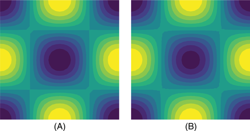
The periodic boundary conditions are imposed in both the x and y directions. The source term is given by . For this problem, we show the results for the , and time . The comparison between the computed results are shown in Figures 3 and 4 which shows the good agreement with the exact solution. The computed results given in Tables 6 and 7 are obtained by using the combination of DIFST scheme, Newton's method and preconditioned SSOR BiCG-stab for time discretization, nonlinear and linear solvers respectively.

| Linear ITs | Nonlinear ITs | error | CPU time (s) | ||
|---|---|---|---|---|---|
| 2.0 | 0.01 | 2237 | 2237 | 1.3174E-03 | 4.9459e+00 |
| 2.5 | 0.01 | 2790 | 2790 | 3.7607E-04 | 6.1735e+00 |
| 3.0 | 0.01 | 3357 | 3357 | 3.9371E-05 | 7.3951e+00 |
| 3.5 | 0.01 | 3924 | 3924 | 1.7006E-05 | 8.6268e+00 |
| 4.0 | 0.01 | 4484 | 4484 | 2.0979E-06 | 9.8551e+00 |
| 4.5 | 0.01 | 5044 | 5044 | 5.2207E-07 | 1.1071e+01 |
| 5.0 | 0.01 | 5603 | 5603 | 6.4533E-07 | 1.2297e+01 |
| Linear ITs | Nonlinear ITs | error | CPU time (s) | ||
|---|---|---|---|---|---|
| 2.0 | 0.01 | 2237 | 2237 | 1.2364E-02 | 4.9459e+00 |
| 2.5 | 0.01 | 2790 | 2790 | 1.0807E-03 | 6.1735e+00 |
| 3.0 | 0.01 | 3357 | 3357 | 3.0361E-04 | 7.3951e+00 |
| 3.5 | 0.01 | 3924 | 3924 | 1.7649E-05 | 8.6268e+00 |
| 4.0 | 0.01 | 4484 | 4484 | 2.0789E-06 | 9.8551e+00 |
| 4.5 | 0.01 | 5044 | 5044 | 1.4256E-06 | 1.1071e+01 |
| 5.0 | 0.01 | 5603 | 5603 | 1.0012E-06 | 1.2297e+01 |
6.3 Test problem 3: 2D Lid driven cavity flow
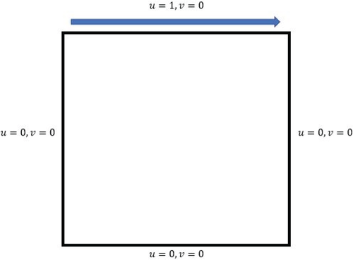
In the following problem, the flow is given by moving the top lid boundary with constant speed with no-slip boundary conditions on the other walls of square domain while the pressure is extrapolated from the interior. The configuration of geometry and boundary condition are shown in Figure 5. The computational domain for this problem is a square with edges of unit length.
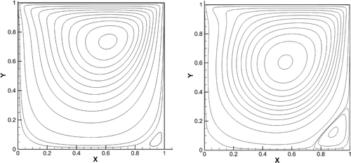
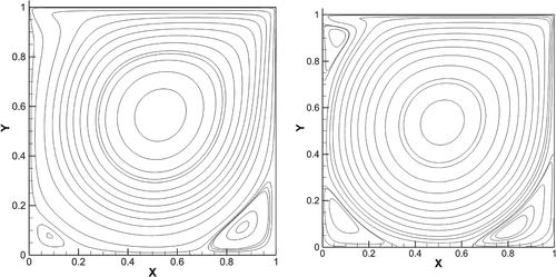
In Figure 6A,B, the vorticity contours at for and are given. Similarly, in Figure 7A,B, the vorticity contours at for and are given. We observed both results have shown good agreement especially in terms of computational cost with the existing results in literature .
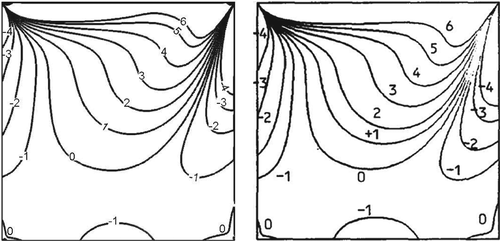
In Figure 8A,B, the comparison of vorticity contours at for are given which shows the good agreement with result in Reference 30.
6.3.1 Numerical stability:
Next, we discuss the numerical stability of the different time discretization schemes. All these results are taken by keeping viscosity fixed , with and from time to . In Table 8, the computational cost is presented in terms of CPU time. We have observed that DIFST scheme is more efficient and stable.
| Scheme | CPU time () | Linear ITs | Nonlinear ITs |
|---|---|---|---|
| DIFST | 2.0188e+02 | 12245 | 245 |
| One step | 2.2251e+02 | 13467 | 298 |
| Crank Niklson | 2.1230e+02 | 20261 | 307 |
| Alexander (order 2) | 3.8680e+02 | 21307 | 516 |
| Alexander (order 3) | 7.2525e+03 | 34532 | 749 |
| Heun's | Fails | Fails | Fails |
| Shu third-order | Fails | Fails | Fails |
7 CONCLUSIONS
This article presents a numerical scheme for solving the two-dimensional unsteady incompressible Navier–Stokes equations by using the conforming finite element method. The diagonally implicit fractional step scheme for the temporal discretization is used. By the damped Newton method, the non-linear system of equation is solved. While the linear system of equations is solved by implementing different linear solver with preconditioners. It is observed that BiCG-stab with preconditioner SSOR gave efficient results based on the number of iterations and error. The accuracy of the scheme is given by computing the error norm. For the time-dependent solution, the robustness and efficiency of the DIFST scheme are demonstrated by comparing it with other time discretization schemes. A comparison of different linear solvers with preconditioners are given in terms of the number of iterations, the error norm and CPU time. The DUNE-PDELab open source software is used for all the numerical computations.
ACKNOWLEDGMENTS
Part of this work was carried out during the visit of S. Raza to the University of Heidelberg under the Post-Bachelor program of HGS MATHCOMP. The support of Prof. Peter Bastian and Mr. Linus Seelinger from IWR is highly acknowledged. The work of A. Shah, A. Rauf was supported by HEC under NRPU No. 7781 and S. Raza by PSF No. 5651.
CONFLICT OF INTEREST
The authors declare no potential conflict of interests.
Biographies

Saad Raza received MS and BS in Mathematics from COMSATS University Islamabad, Pakistan. Currently, he is working as Research Assistant in the Department of Mathematics, COMSATS University Islamabad, Pakistan. His research interests is in Applied Computational Mathematics and Numerical solution of Partial Differential Equations.

Abdul Rauf was a research student at COMSATS University in Islamabad, Pakistan. He does research on numerical techniques for solving systems of nonlinear equations and partial differential equations.

Jamilu Sabi'u is a research student at COMSATS University in Islamabad, Pakistan. He does research on numerical techniques for solving systems of nonlinear equations and partial differential equations. He had almost 30 publications published in reputable journals.

Dr. Abdullah Shah received PhD in Computational Mathematics from Institute of Computational Mathematics, Scientific/Engineering Computing, Chinese Academy of Sciences in 2008. Currently, he is working as Head and Associate Professor in the Department of Mathematics, COMSATS University Islamabad, Pakistan and involved in teaching, research, and administration. His research interests span Applied Computational Mathematics, Modeling Simulations, and Computational Fluid Dynamics. He is the author of several research articles published in reputed journals. Also, he is the recipient of prestigious Erasmus Mundus (EMMA) postdoctoral fellowship at Interdisciplinary Center for Scientific Computing (IWR), University of Heidelberg, Germany, in 2014, "TWAS-UNESCO Associate" (2013–2016) and CAS President's International Fellowship Initiative "Visiting Scientist" (2018–2019) at Chinese Academy of Sciences. He is HEC approved supervisor in mathematics and supervising BS/MS and PhD students.


