An adaptive coupling of finite elements with smooth particle hydrodynamics particles for large deformation fluid–solid interactions
Abstract
This article presents a simple technique to couple the finite element method (FEM) and the smooth particle hydrodynamics (SPH) method in the Lagrangian framework for the simulation of problems involving solids and structures under shock loading that cause large deformations, such as rock blasting. For such problems FEM suffers from mesh distortion and thus requires some numerical corrective measures such as element erosion or remeshing to proceed with the solution. These cause some artificial effects and a sufficient increase in the computational time. Mesh-less particle based methods such as SPH, on the other hand offer the flexibility to handle high-speed motion inherently. But the SPH method is more computationally demanding and requires special treatment for application of boundary conditions. For the simulation of certain process that involve high impact by fluid on solids or structures such as blasting, a coupled FEM-SPH procedure might be more efficient where regions of large deformations are modeled with SPH particles and regions far off are modeled with FEM. An adaptive procedure of coupling FEM-SPH is developed in this work so that highly distorted elements in the model are replaced by SPH particles on the fly but remain linked to the model thus maintaining the consistency in solution. The article provides the details of this adaptive procedure. Validation of this coupling method is done by analyzing a two-dimensional (2D) elastic impact problem and then is applied for the 2D simulation of fragmentation in brittle rocks induced by high impact blast loads from explosions considering a continuum damage model under plain strain conditions. Since detailed three-dimensional (3D) FSI simulations require, even for the lone SPH or FEM solver, quite powerful computer resources, most examples in this article are restricted to two dimensions assuming plane symmetry and can easily be extended for 3D analyses.
1 INTRODUCTION
The finite element method (FEM) has long been the tool of choice for engineers and scientists needing to simulate problems governed by partial differential equations since the theory is well developed and robust. One of the shortcoming of the method is that for problems that involve large deformations the mesh gets highly distorted to a point where accuracy is lost and stability of the method may vanish. Over the years several methods are developed such as mesh rezoning, element erosion, and so forth to do away with badly distorted elements. These methods may provide results but suffers from computational irregularity and increase computational cost. Alternatively, modified FEM such as the arbitrary Lagrangian Eulerian method may be used for such problems with the introduction of convective terms in the governing equations.1
Mesh-less methods on the other hand make an interesting proposition to model such problems since they can handle large deformations inherently.2 One such particle-based method is The smooth particle hydrodynamics (SPH) by References 3 and 4 which has been used extensively to model explosions (free and confined) and problems under high impact loading conditions.5, 6 SPH method was applied to simulate crack propagation7 and recently for blast induced damage.8 But it is more computationally expensive than FEM1 and produces some instabilities when applied to problems of deforming solids. Furthermore, application of Neumann type boundary conditions is also a tedious process in this method. It must be mentioned here that the Boundary-Element Method that works by discreatizing the boundary of the domain alone, an advantage that is off-set by the difficulties associated in integrating the Green's function for nonlinear problems.9
To get the best of both methods a coupled FEM-SPH technique is proposed where regions of large deformations are modeled with SPH particles to capture deformations and the remaining regions are modeled with FEM to optimize computational time and seamlessly apply these boundary conditions.
In order to couple the FEM and Mesh-free particle methods contact and attachment between elements and particles needs to be established and the transfer of information between them must be coherent. Some of the proposed algorithms in this direction can be found in the works of References 10-14, and more recently in References 15, 16, and 17.
This work has adopted with suitable modifications of the algorithm proposed by Xiao18 for simulating impact and penetration problems in solids where they treat elements near the coupling interface as imaginary particles to calculate forces on particles from adjacent elements and impose equivalent traction on element edges on the coupling interface in accordance with the particle stress associated with that element. Rock basting is a fluid–solid interaction problem with high impact shock loading followed by expansion of the explosive gas that act on the solid causing large strain near the boundary of the blast hole. Hence it is prudent the explosive material is exclusively modeled with SPH particles. The rock is considered as a Lagrangian material and is solved with FEM under suitable boundary conditions. As the simulation proceeds if any rock element is found to be distorted it is replaced by a equivalent solid SPH particle.
The details of this procedure is given in the following sections and is organized as follows. Section 2 states the basic equations of the SPH method. Section 3 briefly describes the Lagrangian formulation of the FEM. In Section 4, the damage modeled used in this work is presented. In Section 5, the details of the FEM-SPH coupling algorithm is provided and Section 6 presents some numerical example for validation of this method followed by an example of explosion in rocks to which the algorithm is applied.
2 THE SPH METHOD
The SPH method essentially comprises of two fundamental concepts. First, is the integral representation of a function and second is the particles approximation of the problem domain. For through explanation and development one is referred to Reference 19.
2.1 The governing equations
The governing equations of the problem are the basic conservation laws of mass, momentum and energy. The SPH discretized form are:
2.2 Constitutive relation
2.3 Time integration in particle method
2.4 Determination of time step size
Equation (19) multiplied by a tuning factor () was used in this work.
3 LAGRANGIAN FORMULATION FOR LARGE DEFORMATION ANALYSIS
The total Lagrangian formulation is used in this work and the details can be found in Reference 24. Here only a very brief description is given for completeness.
3.1 The generalized– method
3.2 Shock resolution by artificial viscosity
4 DAMAGE MODELING
5 COUPLING OF FEM WITH SPH
The interaction between FEM and SPH methods begins with generation of imaginary particles in the elements that are near the interaction boundary. If an element is found to be severely distorted then it is replaced by a SPH solid particle so that the simulation can complete with generation of cracks and fragmentation of the solid. The basic theoretical concept in Reference 18 is applied with suitable modifications for fluid–solid interaction problems such as to include high impact blast load and is presented here.
It must be noted that the transfer of forces and maintenance of velocity continuity is not explicitly imposed for SPH calculations but is naturally derived from the corresponding adjacent elements in a manner that is highlighted in the following subsections. Furthermore, any reference to the term “stress” implies the Cauchy stress (the true stress) unless otherwise specified. Any form of “stress” that is used in the formulations described in Sections 3 or 2.2) are changed to the Cauchy Stress by suitable relations and then used where ever calculations with “stress” is required.
5.1 Generation of imaginary particles from Interface elements
5.2 Setting properties of imaginary particles
- (a)
The mass and density:
- (b)
The coordinates and velocities:
They are taken as the average of those of the three element nodes.
where R, S, and T are indices of the three nodes of element I - (c)
The radius:
where is the area of element I. - (d)
The smoothing length:
- (e)
The stress:
Is estimated based on the stress at Gauss points.
the subscripts IPi indicates ith imaginary particle and EI indicates Ith element.
5.3 Influence on real SPH particles from adjacent elements near the interaction interface
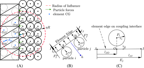
The forces on a particle near coupling interface are evaluated from their adjacent elements located at the FEM boundary and other real particles. The key idea here is to extend the particle approximations to include both real and imaginary particles in the influence domain of each real particle. In such a case the number of particles N in the summation of Equation (1) would be NIP + NRP, where the subscript IP is “Imaginary Particle” and RP denotes “Real Particle.” For example, in Figure 1(A) real particles n1 − n15 and imaginary particles n16 − n20 are considered as neighbors of particle i. It is noted that the imaginary particles are also used in the calculation of strain rates in Equation (14).
5.4 Forces on element nodes from adjacent particles
5.5 Association of SPH particle with element edge
The criterion described above allows some penetration and gap between the element side and its associated particles. The allowed penetration and gap are controlled by constants and . In this work, and are taken as −1 and 1, respectively. This makes the penetration and gap less than the particle radius.
The association between particles and element sides is determined at the beginning of computation. It might change during the computational process. At certain intervals the association between the particles and element edges needs to be redetermined. Since the particles that have been once associated with an element side might get detached from the edge and new particles may take up their place. Hence element to particle association near the coupling interface has to be reevaluated at certain intervals of the computational cycle.
5.6 Adaptive coupling technique
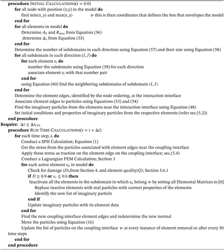
The initial computational model, with the exception of the explosive domain, is entirely composed of elements. During the computation, severely distorted elements are converted to particles and the generated particles near coupling interfaces are linked to the elements by the coupling algorithm.
- Decide on the level of distortion of an element for which it should be converted to an particle.
- Establish afresh the list of elements that are on/near the coupling interface and that are to be treated as imaginary particles.
- Replace distorted elements with their real particle counterparts, and generate the new set of imaginary particles.
- Update the coupling surface of element regions and establish new association between particles and element sides.
This procedure is listed as Algorithm 1.
5.6.1 Determination of elements to be converted to particles
5.6.1.1 Geometrical quality
For triangular element the quality of a triangle is checked as two times the ratio of the radius of the inscribed circle divided by that of the circumscribed circle (an equilateral triangle achieves the maximum possible quality of 1). If is less than a critical value , the element is considered to be distorted and recorded as one converted to a particle.
5.6.1.2 Material quality
An element with damage parameter D = 1.0 is completely incapable of sustaining tensile loads. Hence if for an element D ≥ 0.9 then this element is also recorded as the one to be converted to particle.
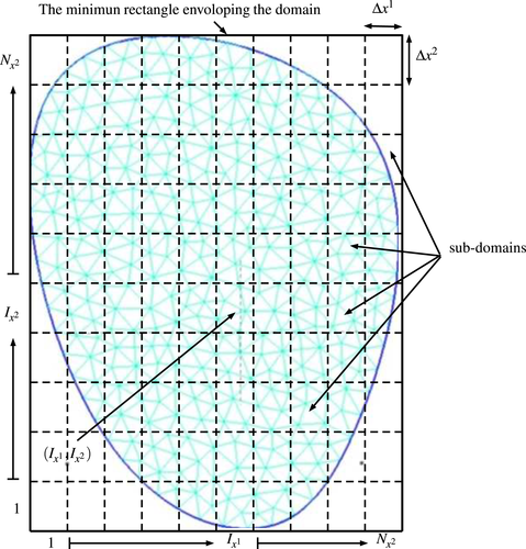
A group-based conversion (GBC) scheme is combined with the quality criterion to determine elements converted to particles. In the GBC scheme, elements of each body are divided into groups at the beginning of the computation. During the computational process, if one or more elements in a group satisfy the conversion criterion, then all elements in that group are converted to particles.
5.6.2 Determination of elements treated as imaginary particles in adaptive coupling
There are generally eight neighboring groups for a given group unless it is a boundary group. Among these neighboring groups, some also should be or have been converted particles. In these cases, they are excluded from the groups treated as imaginary particles.
5.6.3 Update of surfaces of element regions and association between particles and element sides
When subdomains are eroded the FEM-SPH interfaces are updated. At the end of each computational cycle the association between interface particles and interface element edges is checked. If a subdomain is eroded and replaced by equivalent real SPH particle then a new list of particles and element edge is created by the same procedure as described in Section 5.5 above. Similarly the list of imaginary particle created from elements is also updated (cf. Section 5.1). After updating interfaces and generating new real particles from elements the next computational cycle continues.
6 NUMERICAL TESTS AND RESULTS
The above procedures are implemented in a computer code written by the authors using Object Oriented Programming Techniques with C++. In this article, the proposed coupling procedure is verified by analyzing elastic impact on a block and the results are compared with compared with analytic/published solution for verification of the procedure. This article also describes the simulation of an explosion in brittle rock and elaborates the coupling mechanism between product gas particles and solid elements. The details are given in the following sections.
6.1 Elastic impact
For validation of the above coupling algorithm an example calculation is presented here. The example is taken from Reference 24. A block of material is assumed under plane-strain conditions Figure 3 of dimensions L = 5 mm and W = 10 mm. The Young's modulus E = 3.24 GPa, the Poisson's ratio , and the mass density that gives a dilatation wave speed of . The block is not constrained and is loaded by an impact velocity which acts in the positive y-direction on the top surface of the block, at y = +L. The impact velocity is increased linearly from vp = 0 to 10 m s−1 in time tr = 1.0 × 10⁻⁷s. Because of symmetry with respect to the y-axis only one half of the block has been modeled. The mesh consists of 20 × 40 quadrilateral elements for the model simulated only by FEM. For the coupled calculation 800 triangular elements and 2165 particles were used (that includes 1600 real particles and 565 background imaginary particles are discretized as shown in Figure 4(C). The displacements of the nodes on the symmetry axis are constrained in the x-direction. The total time of analysis was 3.09 and time step is set to 1.0 × 10⁻⁸ which satisfies the CFL criterion. The stress contours along the y-axis at different times are given in Figure 4(B), the FEM model and Figure 4(C), the coupled FEM-SPH model. As observed that the plots are almost identical to the one given in Reference 24, Figure 3. The oscillations at the wave front which is due to initiation effects appear before the shock in Figure 4(A) and after the shock in Figure 4(D,E). This can is attributed to the fact that HHT parameters damps out the numerical noise from the nonzero solution more effectively as compared with the central difference method used in Reference 24, Figure 4(A), which has on such dissipative mechanism. Hence this procedure can be used for analyzing high impact problems such as rock blasting, where otherwise handling mesh distortion becomes critical.

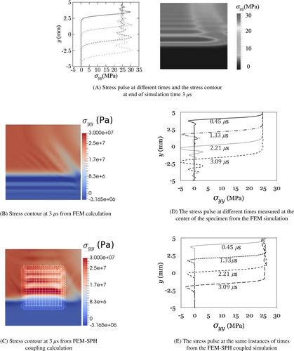
The analytic solution for the magnitude of the stress carried by the pulse is given by which turns out to be equal to 24.81 ≈ 25 MPa. This value is also obtained from our simulations, Figure 4(D), FEM and 4(E), FEM-SPH coupled models. Furthermore, the speed of the stress wave equals the distance traveled by the first peak divided by the elapsed time. From Figure 4(D,E) it is seen that the first peek traveled almost 6.5 mm in from which the calculated speed of the pulse is ≈2166 m s−1, which is close to the dilatation wave speed . All these results indicate that the interaction between the SPH particles and the finite elements in the coupled FEM-SPH procedures works well in simulating an impact phenomenon.
6.2 Blast in square hole
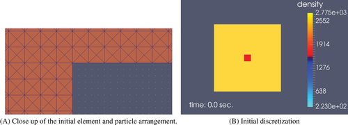
In this example, a simple example of explosive blast using TNT filled in a square hole in a square brittle rock is modeled under plane strain conditions. Here, explosive in the blast hole is discretized with SPH particles and rock part is initially modeled with finite elements as shown in Figure 5(A).
| Material | g cm−3 | VD m s−1 | pCJ (GPa) | A (GPa) | B (GPa) | R1 | R2 | e0 J kg−1 | |
|---|---|---|---|---|---|---|---|---|---|
| TNT | 1.630 | 6930 | 21.0 | 373.8 | 3.747 | 4.15 | 0.90 | 0.35 | 6 ×10⁶ |
| Composition B | 1.717 | 7980 | 29.5 | 524.2 | 7.678 | 4.20 | 1.10 | 0.35 | 8.5 ×10⁶ |
| PBX 9501[9] | 1.844 | 36.3 | 852.4 | 18.02 | 4.55 | 1.3 | 0.38 | 10.2 ×10⁶ |
After detonation, solid explosive particles converts into gas and exert pressure to solid boundary based on Equation (61) The external dimension on the model are 0.1m × 0.1m with a centrally place square hole of size 0.01m × 0.01m of the model. The material properties used were, density = 2500 kg m−3, Young's modulus E = 25 GPa, and Poisson's ratio R = 0.1. The Weibull parameters for damage evolution are taken to be, k = 1.59 × 1038, m = 9.5, corresponding to that of a brittle rock. The hole is filled with TNT of properties given in Table 1.
Initially, the FEM model consists of 39,600 constant-strain triangular solid elements and 576 explosive particles with an arrangement as shown in Figure 5(A). The simulation begins with detonation of explosive particles and the pressure generated by it is applied to the FEM-SPH interface based on the developed coupling algorithm. Then the kinematic variables such as displacements, velocity and accelerations as well as stress are obtained in the finite elements by the method given in Section 5 and at the same time these variables are also updated in the imaginary particles. The variables of the real SPH particles are updated considering all near neighbor real and imaginary particles. The detailed steps of this procedure is given in Algorithm 1.
Figure 5(B) shows the initial discretization of the model with elements and particles and Figure 6(A-G) show the subsequent evolution of the coupling interface in terms of the X-velocity and damage (D) after blast depicting element replacement with time.
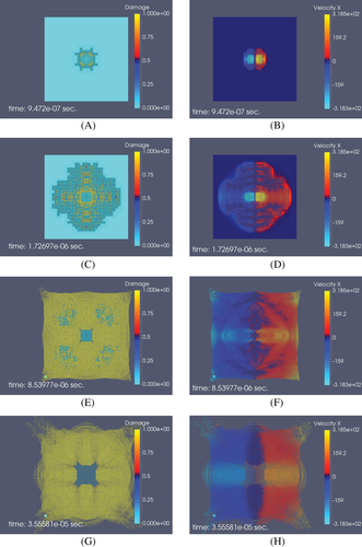
The velocity and damage parameters are further analyzed for three selected elements at three different locations in the model to highlight the efficacy of the developed procedure in replacement of elements by real particles. Figure 7(A) shows the location of these three elements, one at the rock-gas interaction interface (element number 19617), one at the free face (element 19443) and one at the middle of the rock mass. The average nodal velocity profile of these elements and their corresponding velocity profile as particles after damage is shown in Figure 7(B).
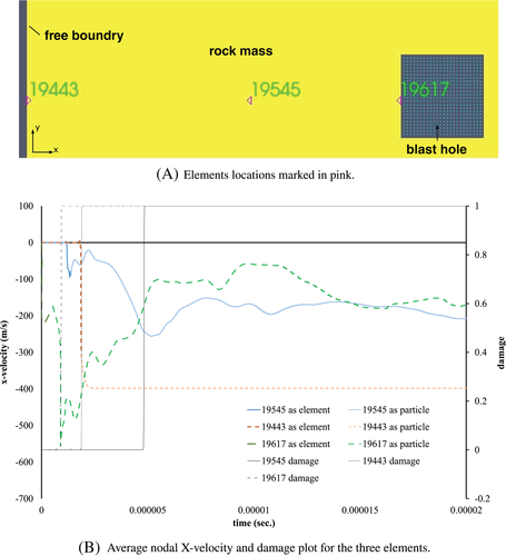
It is observed that the element number 19617, that is closest to the explosive, is damaged immediately after the blast and is eroded from the FEM model. For subsequent calculations it is treated as real SPH particle. Element number 19545 is converted to a real SPH particle at about but is completely damaged at . This is because its erosion from FEM model had occurred due to some other element in its group reaching the threshold value of the erosion criteria at time . The same phenomenon is observed for element number 19443. It is also noted that although element number 19545 is closer to the explosive than the element number 19443 the latter is damaged at a much later stage than the former. This happens because element 19443 is located at the free boundary of the rock mass and thus more susceptible to tensile failure. Figure 7(B) also demonstrates that after damage as the elements are replaced with real SPH particles velocity reached to a more or less constant value.
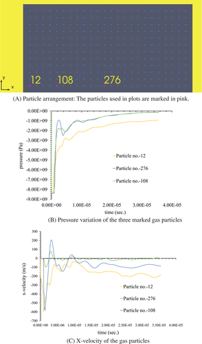
The behavior of gas particles in terms of pressure and X-velocity variations is investigated by considering three particles (cf. Figure 8(A)) located in the middle of the blast hole (particle 276), at the rock-gas interaction interface (particle 12) and at an intermediate point (particle 108) as depicted in Figure 8(B,C). It is observed that all the particles begin with an initial high pressure of about 8.37 × 10⁹ Pa which gradually decays to a residual value with time. A closer look of the pressure data reveals that within a few microseconds after the blast both the pressure and the velocity change rapidly in all the particles (cf. Figure 8(B,C)). This may have happened because of the fact that the initial velocity of the product gas is much larger than that of the surrounding rock mass. As a result, the outward movement of the expanding gas particles is obstructed by the rock causing the particles to return back towards the center of the blast hole. Pressure in the gas particles drops as the velocity of the particles changes its direction. After damage, the rock particles moves outwards keeping up with the velocity of the gas particles. The expansion of the gas causes reduction in the velocity. After some time the variations in velocity and pressure becomes almost negligible. This physical phenomenon is aptly captured by the simulation process.
7 CONCLUSION
This work attempts to alleviate some of the shortcomings of the standard Lagrangian-FEM by introducing particles of the SPH method, on the fly, in regions where mesh entanglement occur. This adaptive coupling algorithm between SPH and FEM is proposed in this article for analyzing high impact shock inducing problems. This is done in a way such that traction and velocity boundary conditions are maintained at the interface boundary, using imaginary particles that complete the kernel approximation for SPH calculations at these boundaries. In addition, a continuum damage model predicts the onset and distribution of failure in solids. As a result, mass and momentum of the total system is conserved. The article also describes the detailed implementation of this adaptive coupling procedure providing an example of elastic bending of beam for validation. Furthermore, an example from blasting of brittle rocks, where fluid–solid interaction is involved under high impact blast load is simulated. The proposed coupling algorithm can be applied to large-scale problems where such fluid–solid interaction is perceived considering geometric and material nonlinearity. However, since there are several process involved (cf. Algorithm 1) when erosion of elements take place this procedure is time consuming and hence effort must be given to develop an efficient algorithm for attaching particles with element edges.
ACKNOWLEDGMENTS
We acknowledge Department of Science and Technology (DST), India and Coal India Limited (CIL) for the partial financial support to this research.
CONFLICT OF INTEREST
The authors declare no potential conflict of interests.
Biographies
Arijit Khan Graduated as Civil Engineer from Jadavpur University Kolkata, India, his interest in Computational Mechanics impelled him to enroll in the PhD program at Indian Institute of Technology, Kharagpur, India, Department of Mining Engineering under the stewardship of Prof. Debasis Deb with very similar passion for the subject. He completed PhD in the year 2019 and is currently involved in simulation software development for use in oil and gas industry.

Dr. Debasis Deb received his PhD degree from the University of Alabama, Tuscaloosa, USA in 1997. Currently, he is serving as a Professor in Department of Mining Engineering, IIT Kharagpur. He has work experience as Research Associate at Korea Institute of Geoscience and Mineral Resources (KIGAM), South Korea for 1 year. Dr. Deb is the recipient of prestigious National Geoscience Award (2013), presented by The President of India, for his works in the area of rock mechanics and ground control. He has published two books and a chapter of a book. He has published over 180 research articles in various national and international journals and conferences and has five patents in his credits.


