Computational analysis of LED circuits based on partial quasi-group rings
Abstract
Since the original idea of Claude Shannon about describing switching circuits by means of Boolean algebras, the working of devices within electric circuits has been modeled in the literature by means of different types of algebras. This paper delves into this topic by dealing with the synthesis and computational analysis of light-emitting diode (LED) circuits through which the electric current is regulated by a set of devices (voltage regulators, single-pole double-throw relays, analog multipliers, capacitors, resistors, and push buttons) whose working is uniquely described by a given partial quasi-group ring, or, equivalently, by a partial Latin square. Some results on the existing relationship among the designed circuits and these algebraic and combinatorial structures are exposed. Furthermore, to illustrate this relationship, we introduce a light switching game whose goal is lighting all the LEDs within a circuit based on a given partial quasi-group ring. The solvability of the game is analyzed by making use of computational algebraic geometry.
1 INTRODUCTION
In 1938, Claude Shannon1 introduced Boolean algebras in electrical engineering to deal with the synthesis and analysis of switching circuits. Recall in this regard that a switch is a device that can interrupt the flow of the electric current through an electric circuit. It has two mutually exclusive states: closed, if the electric current can flow, and open, if otherwise. Based on this fact, Shannon identified switches within an electric circuit with Boolean variables so that the working of such devices is uniquely described by a series of Boolean equations. This would constitute the fundamentals of the binary arithmetic of modern computers.
Since the original work of Shannon, different algebras have been used in the literature to model the working of other types of devices within electric circuits. Thus, for instance, Bryant2 remarked the role that matrix algebra plays to model the different connections within electric circuits containing resistors, capacitors, and inductors by means of incidence matrices of graphs representing such circuits. Much more recently, electrical networks consisting only of resistors have been modeled by means of the so-called electrical Lie algebras.3, 4 All these models are based on lumped circuits, for which the electrical impedance only depends on time but not on the spatial distribution of the devices, that is, current through and voltage across conductors do not vary. On the other hand, complex algebra5 and geometric algebra6, 7 provide efficient approaches to model the flow of electric current through devices within distributed circuits, for which the electrical impedance also depends on space.
This paper delves into the algebraic representation of devices within lumped circuits. More specifically, we focus on the synthesis and computational analysis of light-emitting diode (LED) circuits through which the flow of electric current is regulated by a set of devices (voltage regulators, single-pole double-throw (SPDT) relays, analog multipliers, capacitors, resistors, push buttons, and, of course, LEDs) whose topology and working are uniquely described by a given partial quasi-group ring, or, equivalently, by a partial Latin square. The characterization of such circuits according to their structural properties enables us to endow partial quasi-groups and partial Latin squares with new invariants that make easier their classification. Currently, the search of such invariants constitutes an open and active problem.8-11 The study of combinatorial designs by means of electric circuits was already considered by Brooks et al12 and Tjur13. Further, Kumar et al14 dealt with the completion problem of partial Latin squares motivated by its possible application to light path assignments and switch configurations. Much more recently, Vaskouski and Zadorozhnyuk15 have dealt with electric circuits associated to the Cayley graph on a symmetric group, which were based in turn on a previous design of interconnection networks based on finite groups.16
In the literature, (partial) quasi-groups and (partial) Latin squares have motivated the introduction and later analysis of different types of combinatorial games.17-23 This paper also delves into this topic. Thus, to illustrate the existing relationship among the designed LED circuits and the algebraic and combinatorial structures from which they arise, we introduce a light switching game whose goal consists of lighting all the LEDs within one such a circuit. Similarly to other types of light switching games,24-28 we make use of computational and algebraic tools to analyze the solvability of the game. More specifically, we make use of computational algebraic geometry to deal with such a problem. This approach has already been used in the literature to analyze the solvability of other games based on combinatorial designs29-32
This paper is organized as follows. In Section 2, we expose some preliminaries on electric circuits and partial quasi-group rings. Section 3 deals with the synthesis and analysis of our proposal of an LED circuit based on a given partial quasi-group ring. Finally, in Section 4, we introduce and analyze computationally the mentioned light switching game that is based on such circuits.
2 PRELIMINARIES
Let us review some basic concepts and results on electric circuits and partial quasi-group rings that are used throughout this paper. We refer the reader to the manuscripts33-35 for more details on both topics.
2.1 Electric circuits
Electric charge is a basic property of matter that is carried by the elementary particles within each atom: Electrons carry negative electric charge, whereas protons carry positive one. Thus, the electric charge of a given piece of matter is that one carried by its protons minus that one carried by its electrons. According to the International System of Units (SI), the unit of quantity of electric charge is the coulomb, which is approximately equivalent to the charge of 6.242 × 10¹⁸ protons.
A point charge is the electric charge at a given point of matter. It exerts a force on any other point charge, which is repelling if both charges are of the same type (positive or negative) or attracting if otherwise. The voltage between both points is the work required to move a coulomb between them. Its SI unit is the volt.
An electric current is a flow of electric charge derived from the movement of electrons through a given electrical conductor. Depending on the conductive material or the environmental conditions, every electrical conductor presents a constant opposition to any electric current through itself, which is called resistance.
An electric circuit is a circular path made of electrical conductors through which an electric current flows. This is parallel if there are branches in the path. A junction is any point within a parallel circuit where three or more branches meet together. Further, the impedance of an electric circuit is the measure of the opposition that such a circuit, or a part of it, presents to the electric current. This includes the resistance of electrical conductors. Finally, the synthesis of an electric circuit consists of designing it from a given input-output relationship, whereas its analysis consists of determining such a relation by means, for instance, of an operation table where all the currents and voltages are exposed.
If the electric charge flows always in the same direction through a circuit, then the initial point from which the electrons enter into the circuit is its source
 , whereas the final point to which the electrons flow and leave the circuit is its ground
 . Both points constitute the terminals of a voltage source, which maintains a fixed voltage anywhere in the circuit, regardless of the existing current or impedance.
 and
and
 constitute the load of the circuit. This is formed by different devices controlling the electric current through the circuit or the voltage between its points and a set of wires connecting them. Each device has at least one input terminal into which the current flows from the circuit and at least one output terminal from which the current flows towards the circuit. Regardless of their types, the way in which the devices are interconnected constitutes the topology of the circuit. The following devices are used throughout this paper.
- A battery is a voltage source that converts chemical energy into electrical energy in the form of voltage, which in turn makes electric current to flow.
- A voltage regulator provides a fixed output voltage of a preset magnitude that remains stable regardless of the input current or voltage.
- An SPDT relay modifies the direction of the current. It has an input terminal and two output terminals.
- An analog multiplier produces a voltage that is equivalent to the product of two independent voltages from its two input terminals.
- A push button enables the current to flow through the circuit when it is pressed and held, and interrupts the current when it is released.
- A capacitor stores up to a certain charge at up to a certain voltage. Once it is fully charged (and hence, its maximum voltage is reached), the current stops flowing through the branch of the circuit where the capacitor is.
- A resistor introduces resistance into the circuit.
- A diode enables the current to flow freely through it in only one direction. An LED constitutes a light-emitting diode.
Every circuit is schematically drawn as a diagram where devices are represented by conventional symbols (see Figure 1, where terminals are represented by the symbol ∘). A schematic of a parallel circuit is shown in Figure 2, where junctions are represented by the symbol •. The labels therein are explained in Section 3.


2.2 Partial quasi-group rings
A quasi-group is a pair (Q,·), where Q is a finite set endowed with a binary operation · such that, if any two of the three symbols in the equation a·b = c are given as elements in Q, then the third one is uniquely determined. The cardinality of Q is the order of the quasi-group.

 , then Q is called trivial. Otherwise, it is called nontrivial. Further, if
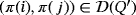
 , then Q is indeed a quasi-group. Two partial quasi-groups (Q1,·) and (Q2,∘) of the same order are said to be isomorphic if there exists a bijection π:Q1→Q2 such that π(i)∘π( j) = π(i·j), for all
 .
.The multiplication table of a partial quasi-group (Q,·) of order n constitutes a partial Latin square of the same order, that is, an n × n array in which each cell is either empty or contains one symbol chosen from the set Q, such that each symbol occurs at most once in each row and in each column. If there are not empty cells, then this constitutes a Latin square of order n. In such a case, the pair (Q,·) is, in turn, a quasi-group. Isomorphisms of partial quasi-groups are uniquely related to a same permutation of the rows, columns, and symbols of its related partial Latin square. The distribution of Latin squares into isomorphism classes is known for order n ≤ 11,37-39, and that of partial Latin squares has been explicitly computed for order n ≤ 6.40-42
In 1944, Bruck33 introduced the concept of quasi-group ring based on a quasi-group (Q,·) as an n-dimensional algebra
 of basis β = {e1,…,en} over a ground field
 , so that its multiplication operation [.,.] is linearly defined as [ei,ej] = ei·j, for all i,j ∈ Q. We call β the natural basis of
 . The notion of a partial quasi-group ring is similarly defined once Q is allowed to be partial. In particular, (partial) quasi-group rings based on isomorphic (partial) quasi-groups are also isomorphic. Different types of partial quasi-group rings have been studied from a computational point of view.43-45
3 LED CIRCUITS BASED ON PARTIAL QUASI-GROUP RINGS
Let
 denote the set of nontrivial partial quasi-groups over the finite set [n]: = {1,…,n} having as a multiplication table a partial Latin square whose main diagonal is formed only by empty cells. This section deals with the synthesis and analysis of a proposal of LED circuit
 based on a given partial quasi-group
 .
.
3.1 Synthesis
 . In addition to the battery
 , this consists of
- a voltage regulator VRi and a relay SPDTi, for each i ∈ [n];
- an analog multiplier Mij and a push button Bij, for each pair
 ;
; - a capacitor Ci, a resistor Ri, and an LED Li, for each positive integer
 ; and
; and - a (multiple) push button FB, which we call final button.
 whenever the ith output terminal of a device D is connected to the jth input terminal of a device D′. If a terminal is unique as input or output in the device under consideration, then we remove the corresponding index. Further, we denote
 and
and
 whenever the device D is connected to the source or the ground, respectively. Thus, the topology of the LED circuit
 is described as follows. For each pair
 , the following sequence holds.
 (1)
(1)
 be the partial quasi-group having the following partial Latin square as multiplication table:
 is described by means of the following three sequences:


 .
.

3.2 Analysis
To perform the analysis of the LED circuit
 that we have just described in the previous subsection, we introduce the following definition.
Definition 1.Let
 ,
,
 be a field of characteristic
 and
and
 so that ri > 0, for all i ∈ [n]. We denote
 as the LED circuit
 working as follows.
- The battery voltage is
 volts whenever
 . Otherwise, it is
 .
. -
The current flows from the source towards the capacitors (and toward the LEDs if the final button were switched on) once the next actions are sequentially made.
-
Each voltage regulator VRi is regulated so that a stabilized voltage of
 volts is provided from its output terminal, where
 .
. - A partition {S1,S2} of the set [n] is defined so that, for each i ∈ [n] and each k ∈ {1,2}, the relay SPDTi is switched towards its kth output terminal if and only if i ∈ Sk.
- A subset
 is defined so that the push button Bij is pressed if and only if (i,j) ∈ B1 × B2.
We define a pulse within
 as the complete set of physical effects produced after all the previous actions are sequentially made. That is, the recharge of capacitors and, if the final button were switched on, the lighting of LEDs.
 -
-
The maximum voltage that each capacitor within the circuit can store is
 volts. Moreover, an electrical spark is produced whenever such a maximum voltage is reached, so that the capacitor under consideration is fully discharged, without any loss of its storage capacity.
Hence, each time that a push button Bij is pressed, held, and released, the original voltage of ci·j volts stored within the capacitor Ci·j becomes
volts.
- If the final button is switched on, then, for each i ∈ [n], the resistance of the resistor Ri reduces
 volts the voltage of the capacitor Ci. Then, these volts flow from Ci towards the LED Li. Remark that, within each pulse, only one such a reduction of voltage is produced from each capacitor. In practice, the maximum voltage required by each LED Li to be lighted without burning out are these ri volts. The more voltage is provided to the LED the more luminous intensity emits.
Let us illustrate the previous definition with an example. In its formulation and from here on, we use the conventional notation
 to denote the finite field of characteristic k.
Example 2.Let Q be the partial quasi-group described in Example 1 and let us consider the LED circuit
 . According to Definition 1, such a circuit has the following properties.
- Its battery voltage is vmax = 2 volts.
- To produce a pulse within the circuit, its three voltage regulators can only be regulated so that either zero volts or one volt are provided as output from each one of them.
- The storage capacity of each one of its two capacitors is one volt. Moreover, if a second volt comes into a charged capacitor in a pulse, then an electrical spark is produced so that the capacitor becomes fully discharged.
- The resistance of each one of its two resistors is also one volt. As a consequence, all the capacitors of the circuit are fully discharged after the final button of the circuit is pressed.

Let
 be the partial quasi-group ring related to a partial quasi-group
 , and let {e1,…,en} be the natural basis of
 . From here on, we say that two vectors
 and
and
 in
in
 are compatible if aibi = 0, for all i ∈ [n]. The following result establishes how the working of the LED circuit
 can be algebraically represented by multiplying compatible vectors within
 .
.
Lemma 1.The working of the LED circuit
 is uniquely determined by the partial quasi-group ring
 .
.
Proof.Keeping in mind the synthesis and working of the circuit, let us see how, after a pulse is produced, the new voltage that is stored by the capacitors within
 is uniquely determined by making use of the partial quasi-group ring
 .
.
For each i ∈ [n], let ai (respectively, bi) be the amount of volts that are stabilized by the voltage regulator VRi whenever i ∈ S1 (respectively, S2), and zero, if otherwise. If {e1,…,en} is the natural basis of
 , then we consider the vectors

 . Hence, the coefficient of each basis vector ei·j in
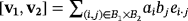 is the voltage that is attempted to be stored in the capacitor Ci·j whenever the push button Bij is pressed, held, and released. Thus, the distribution of the total recharge of voltage into the capacitors within
 is uniquely determined by the corresponding coefficients in the product [v1,v2]. Moreover, the loss of the whole voltage within each capacitor, which is due to the electrical sparks that are produced each time that it is fully charged, is algebraically represented by taking modulo
 , as it is indicated at the end of the third statement in Definition 1.
Further, the sum of different products of compatible vectors within the partial quasi-group ring
 represents a series of pulses within the circuit, so that each addend constitutes an independent recharge of capacitors. When the final button is pressed, the whole stored charge flows from the capacitors towards the LEDs within the circuit.
Finally, the resistance of resistors avoiding LEDs to burn out can be algebraically represented as a convenient subtract, as it is indicated in the fourth statement in Definition 1.
Example 3.Let Q = ([3],·) and
 be the partial quasi-group and the LED circuit that we have respectively described in Examples 1 and 2. Moreover, let {e1,e2,e3} be the natural basis of the partial quasi-group ring
 . Let us consider, for instance, the compatible vectors e1 and e2 + e3. Their product within
 is
is

Let us focus now on the pulse corresponding to the following product of compatible vectors.

Observe at this point that, if the pulse represented by the product [e2,e1] is produced immediately after that one represented by the product [e1,e2 + e3], then two volts come into the capacitor C2. As a consequence, if the final button is not pressed, then an electrical spark is produced so that the mentioned capacitor becomes fully discharged. Remark how this fact is algebraically represented once both products are added. To this end, keep in mind that the characteristic of the ground field
 is two.


Proposition 1.The topology and working of the LED circuit
 only depends on the isomorphism class of the partial quasi-group Q.
Proof.Let Q′ = ([n],∘) be a partial quasi-group that is isomorphic to Q by means of an isomorphism π:[n]→[n]. In particular,
 implies that
 because
 if and only if
 ; hence, the main diagonal of the partial Latin square associated to Q′ is only formed by empty cells, as it happens with that of Q.
Furthermore, each device in the circuit
 that is labeled as Di, with D ∈ {VR,SPDT,C,R,L} (respectively, Dij, with D ∈ {M,B}), is uniquely related to the device of the same type in the circuit
 that is labeled as
 (respectively,
 ). This relation is well-defined because
 if and only if
 . Thus, the interconnection among devices is preserved; hence, the topology of
 coincides with that of
 , where r′ = (rπ(1),…,rπ(n)).
Finally, let {e1,…,en} and
 be the respective bases of the partial quasi-group rings
 and
and
 . Both algebras are isomorphic by means of the isomorphism
 that is linearly defined so that
 , for all i ∈ [n]. Thus, the working of the circuit
 is uniquely determined by the partial quasi-group ring
 as in the proof of Lemma 1 once each basis vector ei is replaced with
 . Hence, the working of both circuits
 and
and
 coincide.
Proposition 1 enables us to ensure that our designed LED circuits can be used to define new isomorphism invariants that make easier the distribution into isomorphism classes of the set
 and, hence, of partial Latin squares having empty cells in their main diagonal. To deal with this, we introduce the following definitions.
Definition 2.We say that the LED circuit
 has a clear configuration if it satisfies the following physical conditions:
- All its capacitors are uncharged.
- Its final button is switched on. The rest of the push buttons are switched off.
- All its LEDs are off.
Then, we define the luminescence of
 as the maximum number
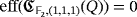
 of LEDs that can be lighted by producing only one pulse from a clear configuration of the circuit. Further, we define the efficiency level of
 as the minimum number
 of pulses that are required to light all its LEDs by starting from a clear configuration of the circuit, regardless of the luminous intensities that they emit. If such a lighting is not possible whatever the number of pulses is produced, then we define
 .
.
Let us illustrate the previous definition with a pair of examples.
Example 4.Under the assumptions of Example 3, we have that
 , because [e1,e2 + e3] = e1 + e2. This implies readily that
 .
.

Example 5.Let
 be the partial quasi-group having the following partial Latin square as multiplication table:

Let
 be a ground field, and let {e1,e2,e3} be the natural basis of the partial quasi-group ring
 . Moreover, let

 . From the definition of Q, we have that

 , whatever the triple
 is. As a consequence,
 .
.In fact,
 , whatever the ground field
 and the triple r are because the following product of compatible vectors always hold.


The reasoning exposed in Example 4 concerning how a maximum luminescence is uniquely related to an efficiency level of value one is established in the following lemma.
Lemma 2.Let
 ,
,
 be a field and r = (r1,…,rn) be a tuple in
 so that ri > 0, for all i ∈ [n]. Then,
 if and only if
 .
.
Proof.According to the synthesis of
 , the cardinality of
 coincides with the number of LEDs within the circuit. Hence, the result follows readily from the definition of luminescence and efficiency level.
Lemma 3.Let
 and
and
 . Then,
 if and only if
 .
.
Proof.Since
 , it is not possible to light all the LEDs of the circuit by producing only one pulse from a clear configuration. Moreover, under our assumptions, whatever two compatible vectors we choose to produce a pulse from a clear configuration of the circuit, the only volt that can be stored at most in any of its discharged capacitors is immediately used to light the corresponding LED. As such, we get again a clear configuration after any such a pulse; hence,
 .
.
The following example illustrates Lemma 3.
Example 6.Under the assumptions of Example 5, if we consider the ground field
 , then the second assertion of Lemma 3 implies that
 . Further, if we consider the finite field
 as the ground field, then
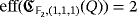 . To see it, it is enough to consider the consecutive pulses associated to the following two products of compatible vectors:
- Pulse 1: [2e1,e2 + e3] = 2e1 + 2e2.
- Pulse 2: [e2,e1] = e3.
With the first pulse, two volts are stored in each one of the capacitors C1 and C2. Immediately after, since the final button of the LED circuit is considered to be switched on, one volt is discharged from each one of these two capacitors to light both LEDs L1 and L2. After this first pulse finishes, both LEDs turn off and exactly one volt is stored in each one of the mentioned capacitors. Then, with the second pulse, a volt is stored in the capacitor C3. Immediately after, one volt is discharged from each one of the three capacitors of the circuit to light simultaneously all its LEDs.

The following result enables us to focus on a representative for each isomorphism class of the set
 to determine the set of possible luminescence and efficiency levels of the LED circuits
 , for any partial quasi-group Q ∈ Qn, any field
 , and any n-tuple
 .
.
Theorem 1.Both the luminescence and the efficiency level of LED circuits based on partial quasi-group rings constitute isomorphism invariants of the partial quasi-groups on which such partial algebras are based.
Proof.Let Q = ([n],·) and Q′ = ([n],∘) be two partial quasi-groups in the set
 that are isomorphic by means of an isomorphism π:[n]→[n]. Let
 be a field and r = (r1,…,rn) be a tuple in
 so that ri > 0, for all i ∈ [n]. From the proof of Proposition 1, we are interested in the study of both LED circuits
 and
and
 , where r′ = (rπ(1),…,π(n)).
Let {e1,…,en} and
 be the respective natural bases of the partial quasi-group rings
 and
and
 . Concerning the luminescence of both circuits, suppose that
 . The proof of Lemma 1 involves the existence of two compatible vectors v1 and v2 in
 , a subset I = {i1,…,il}⊆[n] and a subset
 such that
 . Let
. Let
 be the isomorphism that is defined as in the proof of Proposition 1. Then,
 and
and
 are two compatible vectors in
 such that
 ; hence,
 . A similar reasoning implies that
 ; hence, the luminescence of both circuits coincide.
Now, concerning the efficiency level of both circuits, if
 is known, then either there exists a series of sequential pulses producing the lighting of all its LEDs (if it is positive) or such a lighting is not possible at all (if otherwise). In the first case, it is enough to consider exactly the same sequential pulses for the circuit
 once a convenient relabeling of devices is done in a similar way to that one described in the proof of Proposition 1. Finally, to deal with the second case, suppose that
 . According to the first exposed case, the efficiency level of the circuit
 should coincide with that one of the circuit
 , which is not possible because, from the hypothesis,
 .
.
To illustrate the characterization of isomorphism classes of quasi-groups within the set
 by means of their corresponding luminescence and efficiency level, we focus on the case n = 2. From the known 20 isomorphism classes of partial quasi-groups of order two,42 the following partial Latin squares constitute representative multiplication tables of the five isomorphism classes of the set
 .
.

Table 1 shows the luminescence and efficiency level of these five isomorphism classes. All the exposed values are easily checked.

| Q |
 |
 |
|---|---|---|
| L1 | 1 | 1 |
| L2 | 1 | 1 |
| L3 | 1 | 1 |
| L4 | 1 | 0 |
| L5 | 1 | 0 |
4 A LIGHT SWITCHING GAME
 that is based on a given LED circuit
 , with
 . The outline of the game is described as follows.
- Requirement: A LED circuit
 having a clear configuration.
 - Description of a game turn: A pulse within the circuit is produced by the player.
- Goal: To light all the LEDs of the circuit.
 is solvable (that is, a winning strategy exists) if and only if
 . In what follows, we study the solvability of the game by focusing on the assumptions described in the second assertion of Lemma 3. That is, we consider the particular case in which
 and
and
 . According to that result, the game
 is solvable if and only if
 (2)
(2) . Similarly to the reasoning exposed in Example 5, let us consider the following two generic compatible vectors in
 .
.

 (3)
(3)

The feasibility of both Conditions 3 and 4 is therefore a necessary and sufficient condition to ensure the solvability of our game. Moreover, the number of 2n-tuples (a1,…,an,b1,…,bn) satisfying both Conditions 3 and 4 constituting the number of ways in which the game
 can be solved. Let us illustrate these facts with an example.
Example 7.Let
 be the partial quasi-group having the following partial Latin square as multiplication table:

According to the exposed remarks, the number of solutions of the game
 coincides with the set of tuples
 that satisfies the following system of equations


 :
:

 can be solved by means of only one pulse.

5 CONCLUSION AND FURTHER WORK
In this paper, we have introduced a design of LED circuits whose working is uniquely described by a given partial quasi-group ring. Two new isomorphism invariants of partial quasi-groups having only empty cells in the main diagonal of their multiplication tables have also been introduced, which make easier their possible distribution into isomorphism classes.
Even if some preliminary results have been exposed about the effect that known algebraic aspects have in the designed circuits, much further work is required to unlock the potential behind our proposal.
The light switching game described in Section 4 has been implemented into an interactive and dynamical worksheet in the open source GEOGEBRA.46 This is available online in the official repository of this software, at the address https://www.geogebra.org/m/VKMNFY68.
Biographies

Raúl M. Falcón PhD, is an associate professor with Universidad de Sevilla, Seville, Spain. He received the PhD degree in mathematics from Universidad de Sevilla in 2005. His research interests include the study of Latin squares and related structures and the classification of finite-dimensional algebras into isotopism classes.

Juan Núñez PhD, is a tenured professor with Universidad de Sevilla, Seville, Spain. He received the PhD degree in mathematics from Universidad de Sevilla in 1991. His research interests include the study of Lie groups and algebras, discrete mathematics, and history and divulgation of mathematics.