Elucidation of Droplet Formation Mechanisms by Vibrating Mesh Atomizers
Abstract
The research discusses the droplet formation mechanism in vibrating mesh atomizers. These atomizers, commonly used for particle generation in spray dryers or in inhalation devices, are characterized by resonance frequency, volume flow rate, droplet size distribution, and atomization efficiency. It was found out that the droplet size distribution was independent from the volume flow rate. Moreover, the atomization efficiency of this type of atomizer is comparable to that of pneumatic atomizers. The volume flow rate is modeled using the Bernoulli equation and the Hagen–Poiseuille law. Theoretical and experimental investigations concerning the droplet formation mechanism have demonstrated that the Rayleigh jet break-up can be assumed to be the mechanism responsible for droplet formation with a metal mesh atomizer.
1 Introduction
The atomization of liquids is a fundamental process [1], which is used in spray drying [2], spray cooling [3], fuel injection [1], coating [4], application of pesticides, colors and varnishes [5], inkjet printing [6], as well as in medical inhalators [7]. Conventional atomization devices like single fluid or twin fluid nozzles or rotary atomizers are often used for these applications [8]. These atomizers use pressure or compressed air or the kinetic energy of a rotating disk to generate droplets [8]. Another atomizer type is the so called metal mesh atomizer (MMA). It converts electrical energy into surface work. The MMA is characterized by a compact design, an affordable price, and easy scalability [9-13]. The applications of MMAs are found in medical inhalers [14] and also in the Büchi Nano Spray Dryer B-90 (BÜCHI Labortechnik AG, Flawil, Switzerland) as atomization device for the production of small particles [15, 16].
In general, MMAs are composed of a piezoelectric ceramic and a perforated thin metal sheet. The MMA investigated in this work is assembled with a perforated metal sheet placed between two rings of piezoelectric ceramics (see Fig. 1a). The orifices in the perforated metal sheet have a conical shape, and the side of the MMA with the larger diameter orifice faces the liquid. The piezoelectric ceramic is driven by an applied electric voltage, which in turn causes an oscillation of the perforated metal plate (see Fig. 1a). This results in a volume flow rate depending on the liquid properties, the applied voltage, and the applied frequency.
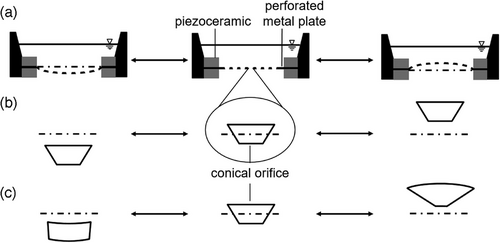
In the literature, different mechanisms for the generation of a volume flow, respectively, for the droplet formation are given [9, 17, 18]. One of the mechanisms is based on the function principle of a valveless pump (see Fig. 1b) [9]. Due to the oscillation of the mesh, the conical orifices are moving up and downwards, which generates a pump effect and therefore a volume flow. Another proposed mechanism contributing to the volume flow is based on the deformation of the conical orifice during oscillation (see Fig. 1c). During the upward movement of the membrane, the diameter of the larger opening of the conical orifice increases, and the orifice is filled with liquid. For the opposite movement, the volume of the conical orifice decreases and the liquid is pushed out. This mechanism is called dynamic cone angle (DCA), and the droplets are generated directly at the surface of the moving plate [9, 19].
The influence of the DCA discussed in the literature by Cai et al. [9], Zhang et al. [20], and Yan et al. [19] underlined the significance of the DCA. However, Guerra–Bravo et al. [17] stated that the change of diameters of the conical orifices can be neglected. Sharma et al. [18] proposed that the velocity and displacement of the perforated metal sheet are the major parameter that causes atomization.
In general, for ultrasonic atomizers there are two important principles, the capillary wave and cavitation. The capillary waves are generated by a piezoelement and resulting in the detachment of droplets from the crests. The cavitation theory states that during the propagation of the ultrasound wave, the local pressure of the fluid decreases below the vapor pressure, resulting to the formation of vapor bubbles. These vapor bubbles implode and rupture the liquid–gas interface, leading to the atomization of the liquid. Both principles need a submerged piezoelement, which is not the case for the vibrating mesh atomizer [8, 21, 22].
The characterization of the atomization process has been characterized in the literature with various focuses. Cai et al. [9] investigated atomization mechanism with the focus on parameters influencing the volume flow. Therefore, they varied the applied voltage and modeled the volume flow rate to validate the mechanism of the DCA. Moon et al. [23] looked at the frequency tuning an MMA to maximize the volume flow rate. As demonstrated by Yan et al. [19] and Sharma et al. [10], an investigation into the droplet size distributions revealed a mean droplet diameter that is comparable to the small diameter of the conical orifice.
The objectives of this work are to investigate the droplet formation mechanism of MMAs and to characterize them in terms of resonance frequency, volume flow rate, droplet size distribution, and atomization efficiency. Furthermore, a model describing the volume flow rate as a function of the applied voltage at the resonance frequency will be presented.
2 Materials and Methods
In this study, the liquids used in the experiment are demineralized water and water–glycerin mixtures. Glycerin was purchased from Carl Roth, Karlsruhe, Deutschland. Experiments were carried out with the MMA SMMOD20F113H8 from Steiner & Martins, Davenport, Florida, USA. The MMA is composed of two piezoelectric ceramic rings, which have an outer diameter of 2.0 cm and an inner diameter of 1.2 cm. Between these piezoelectric rings a circular, perforated metal sheet is placed. The achievable displacement/force with a stacked piezoelement is proportional to the number of used piezoelements [24]. The influence on the atomization process is a higher volume flow compared to a single actuator due to the larger displacement/force. The orifices have a conical structure with a larger diameter dL of 24.5 ± 1.6 µm and a small diameter ds of 7 ± 0.35 µm (x̄ ± s). The metal sheet has a diameter of 1.2 cm and a thickness of 66 µm. The number of orifices is 2668 ± 41. The piezoelectric ceramic material is equivalent to PZT-5A, and the resonance frequency specified by the manufacturer is 113 kHz [25].
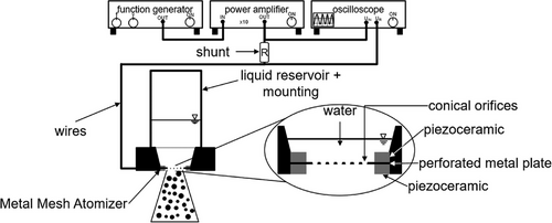
The operating setup is shown in Fig. 2. It consists of a programmable function generator PSG 9080 from Joyt-it (SIMAC Electronics, Neukirchen-Vluyn, Germany), an oscilloscope MSOX30145T from Keysight Technologies (Santa Rosa, California, USA), a power amplifier Pendulum P200 (Pendulum, Drottningskär, Sweden), and the MMA enclosed in a 3D-printed holder with a silicone ring used as a sealing. The signal from the function generator is amplified by the power amplifier, and the oscilloscope used to measure the voltage of the amplified signal. Furthermore, the electric current is measured via the voltage across the current shunt. The liquid circulates from a storage tank through a gear pump to the liquid reservoir above the MMA (constant fill level) and backwards to the liquid tank. The liquid level is kept constant with the aid of an overflow drain. The storage tank is place on the scale Sartorius Basic (Sartorius Lab Instruments, Göttingen, Germany), which enables the gravimetric determination of the throughput.
The droplet size distribution was measured with a laser diffractometer (Spraytec, Malvern, Worcestershire, United Kingdom). Local velocities and droplet size distributions were determined with a Phase Doppler anemometer (PDA) FiberFlow (Dantec Dynamics, Skovlunde, Danemark) with transmitting and receiving optics 57 × 80. The velocity of the vibrating mesh was determined with the vibrometer IVS-500 Polytech (Waldbronn, Germany).
3 Results and Discussion
3.1 Characterization of MMA
The MMAs are commonly operated at their resonance frequency, as this ensures maximum oscillation amplitude relative to off-resonance conditions [24]. It can be expected that at this operation point the largest volume flow rate could be reached. Therefore, it is needed to determine the resonance frequency of the MMA via a frequency sweep, where the frequency is varied, whereas the voltage amplitude remains constant.
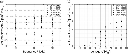
Terminating the frequency sweep, a resonance frequency was found at 95 kHz. From now on, all further experiments were performed at this frequency. The decline of the volume flow rate with increasing Oh-number is explained by a damping effect of the liquid due to higher internal friction in the liquid with higher viscosities. The deviation of the manufacturer-provided resonance frequency is explained by a different measurement set up. The manufacturer used an impedance measurement with no liquid attached to the MMA. A higher mass on top of a piezoelement led to a decrease of its resonance frequency. This underlines the need of the frequency sweep for MMAs.
The volume flow rate is not only depending on the applied frequency but also on the applied voltage. A larger displacement of the MMA, which lead to a higher volume flow rate, is reached with an increased voltage. A variation of the applied voltage between 10 and 90 V peak to peak (Vpp) at the fixed resonance frequency is performed in an amplitude sweep.
Fig. 3b shows the volume flow rate dependency on the applied voltage for various Oh-numbers. First to mention is that a specific voltage level is needed to start the atomization process. With rising Oh-number, the necessary voltage to initiate the atomization increases from 14 to 46 Vpp. After the atomization starts, the volume flow rate shows a sigmoidal course with increasing voltage and converges against to a limit, which depends on the properties of the liquid. In general, the volume flow rate decreases reciprocal to the Oh-number at a constant frequency and applied voltage.
The sigmoidal course of the volume flow rate is explained by the limited displacement of the vibrating mesh. The increase of the voltage to achieve the atomization as well as the reduction of the volume flow rate at higher Oh-numbers can be enlightened by the rise of the internal friction that has to be overcome. In general, the volume flow rate can be varied over a wide range by the applied voltage but also depend on the properties of the liquid.
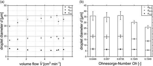
For the characterization of atomizers, in addition to the volume flow rate, the resulting droplet size distribution is essential. It was measured at voltages from 15 to 90 Vpp resulting in volume flow rates between 0.18 and 6.10 cm3 min−1.
In Fig. 4a, the results for the droplet size distribution is expressed by the characteristic values d10,3, d50,3, and d90,3 for water. By increasing the volume flow rate, the median droplet size remains in a range between 16 and 20 µm. This behavior is also observed for the d10,3 and d90,3. Therefore, an averaging of the characteristic droplet sizes over the investigated volume flow rate were carried out. The averaged characteristic droplet sizes for d10,3, d50,3, and d90,3 are shown in Fig. 4b. The reduction in droplet diameter with increasing Oh-number will be discussed in Sect. 3.3.
The atomization efficiency varies with the applied voltage and grows by increasing the voltage and passes through a maximum at about 50 Vpp. Consequently, the phase shift is influenced by the Oh-number, ranging between 30 ° (low Oh-number) and 50 ° (high Oh-number). For the MMA, the atomization efficiency is in a range between 0.05 % for high Oh-numbers and 0.17 % for low Oh-numbers (see Tab. 1). In Tab. 1, the MMA is compared to conventional atomizers and shows a similar efficiency as pneumatic atomizer.
3.2 Modeling of the Volume Flow Rate
In order to model the volume flow, it is necessary to establish its relation to the applied voltage and electric power. Generally, the mesh moves in a sinusoidal motion at a fixed frequency, whereas the voltage is used to alter the amplitude, leading to different kinetic energies of the mesh. This is subsequently utilized in surface work as well as in droplet velocity. Assuming a valveless pump, the volume flow rate should be related to frequency, the amplitude, and the cross-sectional area of all orifices in the mesh. However, the flow rate would be related to the mesh and droplet velocity, which were investigated more closely.
The droplet velocities were measured using a PDA in different positions (axial and radial) with respect to the MMA. Therefore, a low excitation voltage of 25 Vpp was used, which was chosen aiming for a low droplet density desired for the PDA measurements.
For visualization purposes, the droplet velocity of the median of the droplet size distribution is shown (Fig. 5) because it allows tracking the velocity of a droplet size present throughout the spray. Three repetitive measurements were made at the aimed positions. The origin of the axial and radial positions is in proximity of the surface and the center of the MMA. The closest distance to the MMA was 18 mm due to the mounting of the MMA.

The image (see Fig. 5) shows a half of the spray cone, where the MMA is located at the top and the spray diverges toward the bottom. The second half of the image represents the droplet velocity with respect to the axial and radial position (see Fig. 5). First, the PDA measurements capture the evolution of the spray cone having no data at high radial positions at low axial distances, whereas numerous droplets were observed in higher radial positions distant from the MMA.
The pressure at the mesh is expressed by the mesh velocity using Bernoulli (Eq. 4), whereas a linear correlation between the excitation voltage and the mesh velocity was found (Eq. 3). This opens the opportunity to predict the volume flow through a vibrating metal mesh based on the excitation voltage.
Using this fundamental approach, the volume flow rate was modeled considering different excitation frequencies (15–60 Vpp) and different Ohnesorge-numbers (Fig. 6a).
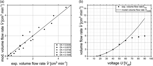
In the parity plot in Fig. 6a, the modeled volume flow rate over the experimental volume flow rate for various Oh-numbers are shown for applied voltages up to 60 Vpp. It can be stated that low deviations are given for lower volume flow rates as well as lower Oh-numbers.
The tendency toward larger deviations at higher Oh-numbers may be related to damping effects. This could be attributed by a Oh-number specific kvelo. Further, the model neglects the influence of the DCA on the volume flow rate, and yet the model overlaps with the experimental data (see Fig. 6). This indicates that the proposed mechanism of a DCA has not a major effect on the volume flow rate because in that case higher deviations can be expected. The same conclusion that the DCA has a minor effect on the volume flow rate was also stated by Guerra-Bravo et al. [17].
In Fig. 6b, the measured volume flow rate and the modeled volume flow rate is given for water over the whole applied voltage range. It presents the agreement between the experimental data and the model up to 60 Vpp and the systematic deviation over a voltage larger than 60 Vpp. This course can be divided into three parts. In the first part, a linear correlation is evident between the mesh velocity and the applied voltage, which gives rise to a quadratic increase in the volume flow rate. This phenomenon can be attributed to a quadratic dependence between the volume flow and the mesh velocity. The second part implies that the mesh has a linear velocity increase up to 60 Vpp, due to the fact that there is an agreement between experiment and the volume flow rate model. The assumption that the mesh has a linear velocity increase can be expanded up to a voltage of 60 Vpp. The following part between 60 and 90 Vpp shows high deviations so that the assumption that the mesh velocity increases linearly cannot be approved. The discrepancy between the experimental and modeled results can be attributed to the inherent properties of the piezomaterial. As demonstrated in Figs. 3b and 6b, the amplitude of the displacement of the MMA is both voltage-dependent and limited. The model assumes a linear relationship between the displacement and the applied voltage, thereby generating the observed discrepancy. Therefore, the given volume flow rate model is limited to the region where the mesh velocity shows a linear velocity increase. The model reaches a coefficient of determination of R2 = 0.962 in the validity range.
3.3 Droplet Formation Mechanism
Further investigations were dedicated to the droplet formation mechanism as it is particularly relevant to the assessment of the performance and limitations of an MMA. Commonly the droplet formation at nozzles is evaluated by imaging looking directly into the break-up of jets or liquid lamella, respectively [1, 29]. This approach is quite challenging in terms of MMAs, as there are hundreds of orifices in close proximity to each other, making the identification of individual processes particularly hard. The excitation frequency, which operates within the higher kilohertz range, necessitates a brief exposure time to avoid the occurrence of blurring. Additionally, the sinusoidal motion of the mesh itself results in its displacement out of the camera's focal plane. Consequently, an indirect method was employed to ascertain the mechanism underlying droplet formation. Therefore, MMA was assumed to be a valveless pump [9] with the certain continuous volume flow, ignoring individual oscillations.
Initial evaluations in this regard combines the throughput of the MMA, the number of orifices in a mesh, and the minimal orifice diameter to the average jet velocity through a single orifice, considering water as a liquid. These values were transferred into Reynolds numbers and visualized considering the Oh-numbers in order to identify the underlying droplet formation mechanism (Fig. 7a).
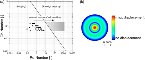
The acceleration was derived from the motion of the MMA, which was found to be a function of the excitation voltage, as previously described. Consequently, the resulting droplet size is dependent on the excitation, which is in contradiction to previous observations. Based on this, the dripping as mechanism for droplet formations has been refused.
Therefore, further investigations are questioning the number of orifices contributing to the volume flow leading to this particularly low Reynolds numbers in the Ohnesorge diagram. Moreover, the individual orifices experience different excitation depending on their position in the mesh due to various vibration modes. This assertion is corroborated by extant literature data examining the velocity distribution at the mesh (Fig. 7b) [17]. Orifices in the center demonstrate high velocity, yet represent a low percentage of all orifices. Accordingly, some orifices do not exceed Δplimit having not enough energy to contribute to the volume flow. Consequently, the number of active orifices should be considerably lower than the total number. Guerra et al. demonstrated that a displacement threshold exists along the radial axis of the perforated metal plate, thereby ensuring that not all orifices are capable of overcoming the minimum pressure difference required for atomization [17]. In the case of Guerra et al., less than 5 % of the perforated area overcome the threshold [17]. If we assume a lower number of active orifices, the velocity of the droplets increases, which shifts the data points in the Reynolds–Ohnesorge diagram in the direction of the jet break-up (We > 4, Fig. 7a, grey box). This regime is characterized by a fixed droplet size distribution of 1.89-fold of the jet diameter [8, 30], which was set to the minimal orifice diameter (7 µm). This results in droplets of a similar size, irrespective of the excitation frequency and voltage.
Based on the measured droplet size distributions, the SMD was calculated using all eight excitation voltages and five liquids and compared to the theoretical value of 13.2 µm, and a high agreement was found (see Fig. 8). However, systematic deviations were observed for the higher viscous liquid, which resulted in a particularly low volume flow, and this was identified as the origin of this deviation. The minimal reduction in droplet diameter with increasing Oh-number can be explained with the assumption made setting the jet diameter equal to the minimal orifice diameter. The higher viscosity at higher Oh-numbers leads to delayed disintegration due to higher viscous forces, which end in a jet diameter reduction. The outcome of this process is a reduction in the droplet size.
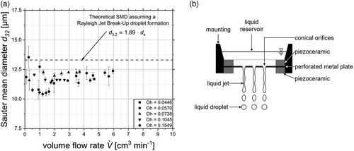
As illustrated in Fig. 8b, the MMA consists of a perforated metal plate and piezoelectric ceramic, which is held in place by a holder during operation. The resulting jets of liquid are illustrated and subsequently breaking up into droplets.
Finally, the droplet formation mechanism of an MMA is based on a pumping action that generates a liquid jet, followed by the well-known jet break-up according to Rayleigh. This leads to a droplet size distribution, which is independent from the excitation voltage, and presumably of the excitation frequency.
4 Conclusion
In this work, three main topics were investigated: first, a method to characterize an MMA regarding to resonance frequency, volume flow, droplet size distribution, and atomization efficiency; second, the modeling of the volume flow rate of an MMA for the given operating conditions; and third, the elucidation of the droplet formation mechanism.
By investigating the relationship between volume flow rate and applied frequency at fixed applied voltage, it revealed that the volume flow rate increases close to the resonance frequency of the MMA. This is shown for Oh-numbers between 0.0446 and 0.1549. Higher Oh-numbers lead to lower volume flow rates. In addition, the volume flow rate at various voltages were measured at the resonance frequency. The course of the volume flow rate showed a sigmoidal shape. Here, higher Oh-numbers resulted in a larger atomization limit regarding the applied voltage, and they lead to a decreasing volume flow rate. The droplet size distribution does not change over a varying volume flow rate in the investigated range. Even a minor effect on droplet size of the Oh-number was observed. The atomization efficiency was in the same range as a pneumatic atomizer and decreased with increasing Oh-number.
A model for the prediction of the flow rate based on the Bernoulli equation and the Hagen–Poiseuille law was established and compared to experimental data, demonstrating a correlation with a coefficient of determination R2 = 0.962. The major parameter causing the atomization is the velocity of the perforated metal sheet. The influence of the DCA mechanism can be neglected in the atomization process.
SMDs were about 1.9 times larger than the outlet diameter of the conical orifices. The indicating dripping as droplet formation mechanism based on the Weber-number was refused due to its dependency on the applied voltage. Further investigations suggest that the number of active orifices contributing to the volume flow could be significantly lower than the total count, potentially less than 10 %. This is due to varying excitation levels among orifices based on their mesh position and different vibration modes. This results in a higher average jet velocity, shifting data points in the Ohnesorge-Reynolds diagram toward the jet break-up regime (We > 4). The droplet formation process was revealed to be a Rayleigh jet break-up.
Acknowledgments
Open access funding enabled and organized by Projekt DEAL.
Symbols used
-
- As, Al
-
- [m2]
-
- a
-
- [m s−2]
-
- d3,2
-
- [m]
-
- d10,3, d50,3, d90,3
-
- [m]
-
- dl
-
- [m]
-
- ds
-
- [m]
-
- e
-
- [–]
-
- f
-
- [Hz]
-
- Ieff
-
- [A]
-
- kvelo
-
- [–]
-
- l
-
- [m]
-
- Lorifice
-
- [m]
-
- Oh
-
- [–]
-
- Psur
-
- [W]
-
- Pel
-
- [W]
-
- Re
-
- [–]
-
- U
-
- [V]
-
- Ueff
-
- [V]
-
-
- [m3 s−1]
-
-
- [m s−1]
-
-
- [m3 s−1]
-
- vmesh,eff
-
- [m s−1]
-
- We
-
- [–]
-
- x
-
- [m]
-
- y
-
- [m]
Greek letters
-
- η
-
- [Pa s]
-
- ρ
-
- [kg m−3]
-
- σ
-
- [N m]
-
- Δpmesh
-
- [Pa]
-
- ζ-
-
- [–]
Sub- and Superscripts
-
- eff
-
- [–]
-
- sur
-
- [–]
-
- el
-
- [–]
-
- velo
-
- [–]
Abbreviations
-
- DCA
-
- dynamic cone angle
-
- MMA
-
- metal mesh atomizer
-
- PDA
-
- Phase Doppler anemometer
-
- SMD
-
- Sauter mean diameter


