Numerical Investigation of Liquid Jet Breakup in Rotary Atomizer
Abstract
This study investigates the breakup behavior of liquid jets in both linear and rotary atomization using numerical simulations based on the volume of fluid (VOF) method. The results reveal the significant role of gas–liquid interactions, with jet curvature, driven by Coriolis and centrifugal forces, playing a crucial role. Various breakup patterns, including primary and satellite droplets, emerge due to nonlinear instabilities. Simulations accurately reproduce experimental droplet size distributions, highlighting the importance of gas–liquid interactions and jet curvature in rotary atomization.
1 Introduction
Liquid jet breakup is a phenomenon of critical importance in various industrial applications, including spray coating, fuel injection, and chemical processing. The mechanisms governing jet breakup have been extensively studied, particularly in the context of linear liquid jets exposed to air crossflows. These studies have demonstrated that breakup patterns transition from dripping to Rayleigh instability-driven modes, ultimately leading to turbulent jetting and atomization, depending on the liquid velocity and surrounding gas conditions [1, 2]. Rayleigh's classical theory [3] has provided a foundational understanding of droplet formation; however, deviations from this linear stability framework have been observed due to nonlinear interactions between fluid instabilities and external forces [4-6].
Although extensive research has been conducted on the breakup of linear liquid jets, the understanding of rotary atomization remains relatively underdeveloped. In rotary atomizers, a liquid film is formed on a rotating surface and subsequently ejected as ligaments or jets from the edge due to centrifugal force. These liquid jets then undergo complex breakup mechanisms influenced by Coriolis forces, surface tension, and aerodynamic interactions [7-9]. Rotary atomization is widely employed in industrial applications, such as electrostatic rotary bell sprayers for automotive painting, where liquid breakup directly affects coating quality and transfer efficiency [10, 11]. Unlike linear jets, rotary atomized jets exhibit unique breakup characteristics, forming sheet-like or ligament-like structures depending on operating conditions such as rotation speed and liquid feed rate. However, despite its industrial importance, the fundamental breakup mechanisms in rotary atomization have not been fully elucidated.
In recent years, numerical simulations have provided valuable insights into liquid jet breakup behavior under controlled conditions. Numerical methods have proven effective in capturing primary atomization processes, particularly in linear jet configurations, by resolving interfacial instabilities and droplet size distributions [12-14]. However, investigations of rotary atomization remain limited. Most studies have focused on post-atomization droplet distributions or simplified models that do not fully capture the detailed breakup processes occurring at the bell edge [15-17]. Experimental studies have demonstrated that shaping air significantly influences the spray pattern and droplet trajectories in electrostatic rotary bell sprayers [18-20]. However, the direct effect of gas–liquid interactions on the breakup process remains poorly quantified, making it challenging to establish precise control over the resulting droplet size distributions.
Advances in computational fluid dynamics (CFD) have enabled the simulation of near-bellcup regions in rotary atomizers, shedding light on some key aspects of the breakup process. Soma et al. [21] predicted liquid film thickness at the bell edge, whereas Izawa et al. [22, 23] analyzed jet formation at low rotation speeds. Shen et al. [17] examined the breakup of pseudoplastic liquid jets under shaping airflows, showing that higher paint flow rates lead to increased formation of liquid threads and droplets. Building on these findings, Saito et al. [24] investigated the effects of viscosity and shear-thinning characteristics on jet breakup, introducing an energy-based framework to quantify gas–liquid interaction forces in crossflow conditions. Although these studies have contributed to the understanding of jet behavior, key aspects of rotary atomization, such as the influence of jet curvature and local gas flow effects on breakup mechanisms, remain unclear.
Despite these advances, several knowledge gaps persist. Previous studies have primarily focused on post-atomization behavior, with limited attention given to the initial breakup mechanisms governing the transition from liquid jets to droplets. Furthermore, while shaping air effects have been experimentally examined, their impact on jet curvature, ligament formation, and the interplay between centrifugal and aerodynamic forces has not been fully addressed. Given these limitations, a detailed numerical investigation is essential to unravel the complex physics governing rotary atomization.
In this study, we investigate the breakup behavior of liquid jets in rotary atomization using direct numerical simulations based on the volume of fluid (VOF) method. Unlike previous studies that primarily focused on post-breakup droplet size, our approach provides a comprehensive evaluation of the breakup process itself, incorporating the effects of jet curvature and gas–liquid interactions. By comparing our results with previous experimental observations [1, 25], we identify the key factors influencing primary and satellite droplet formation in rotary atomization. Our findings provide new insights into the underlying physics of rotating liquid jets and contribute to the optimization of industrial spray processes.
2 Numerical Simulations
2.1 Analytical Objects
2.1.1 Liquid Jet Simulation
To validate numerical simulations of liquid atomization, a previous experiment [1] was replicated. Fig. 1 shows the schematic diagram. A nitrobenzene jet was injected parallel to gravity (x-axis) into water from a nozzle of diameter D. The computational domain (35D × 5D × 5D) was large enough to avoid boundary effects and was discretized into 755 × 50 × 50 non-uniform meshes. A quarter region was calculated with symmetry planes at y = 0 and z = 0. Inflow conditions were applied at the nozzle exit, with outflow at the opposite side. No-slip and slip wall conditions were assigned appropriately. Either fully developed laminar or plug flow was assumed at the inlet. The simulation used a three-dimensional (3D) Cartesian coordinate system. Tab. 1 summarizes the numerical conditions. The study focused on laminar jets, varying injection velocity (0.05–0.4 m s−1) to analyze its effects on breakup patterns and droplet size distribution.

| Nozzle diameter, D | [m] | 1.51 × 10⁻³ |
| Injection velocity, uin | [m s−1] | 0.05, 0.1, 0.2, 0.3, and 0.4 |
| Surface tension coefficient | [mN m−1] | 26.6 |
| Density (dispersed phase) | [kg m−3] | 1208 |
| Viscosity (dispersed phase) | [mPa s] | 2.21 |
| Density (continuous phase) | [kg m−3] | 998 |
| Viscosity (continuous phase) | [mPa s] | 1.004 |
2.1.2 Rotary Atomization Simulation
Fig. 2a shows a schematic of rotary atomization. A liquid film forms on the rotating body's surface and is ejected as a jet, which then breaks up. Due to the high computational cost of simulating the full bell-cup system, this study focuses on the jet elongation region after release, as shown in Fig. 2b. A 3D rotating coordinate system was employed, with the jet introduced at the radial inner boundary (front side). At the base, the circumferential velocity was set to zero as it rotated with the body. The jet's cross-section was assumed circular. A no-slip boundary condition was applied to the front side (excluding inflow areas), whereas the rear side had either a slip wall or open outflow condition. The right and left sides had inflow/outflow or periodic boundary conditions, and the top/bottom were assigned symmetric or slip wall conditions.
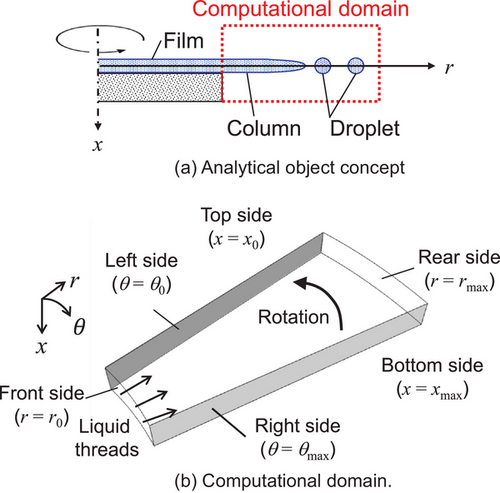
Three cases were examined: Case InOutBC, Case PeriodicBC, and Case Fine (Tab. 2). In Case InOutBC, air was introduced from the right based on a Taylor–Couette flow distribution, influencing the jet's trajectory. Case PeriodicBC applied periodic boundary conditions, allowing jets on the left to influence those on the right, simulating the full circumference of the rotating body. To reduce computational costs, symmetric conditions were applied to the top boundary, limiting the domain to half of the bell-cup region. In Case Fine, a higher-resolution mesh was used to improve accuracy in capturing atomization effects on jet breakup (Tab. 3), while maintaining the same computational domain size. These meshes are significantly finer than those used in Saito et al. [24, 26], ensuring a more detailed representation of gas–liquid interactions. The physical properties, jet diameter, and spacing were based on literature values [25]. In Cases InOutBC and PeriodicBC, gas–liquid interactions affecting jet trajectory were examined, whereas Case Fine provided a detailed analysis of breakup characteristics.
| Case InOutBC | Case PeridiocBC | Case Fine | |
|---|---|---|---|
| Geometry | |||
| x0, xmax [mm] | 0, 0.5 | 0, 0.5 | −0.5, 0.5 |
| r0, rmax [mm] | 35, 38 | 35, 38 | 35, 41 |
| θ0, θmax [degree] | 0, 2.45 | 0, 1.8 | 0, 1.8 |
| Division number | 35 × 300 × 245 | 35 × 300 × 245 | 100 × 900 × 270 |
| Boundary conditions | |||
|---|---|---|---|
| Top side (x = x0) | Symmetry | Symmetry | No-slip wall |
| Bottom side (x = xmax) | No-slip wall | No-slip wall | No-slip wall |
| Front side (r = r0) | Inflow and no-slip wall | Inflow and no-slip wall | Inflow and no-slip wall |
| Rear side (r = rmax) | No-slip wall | Outflow | Outflow |
| Left side (θ = θ0) | Inflow | Periodic | Periodic |
| Right side (θ = θmax) | Outflow | Periodic | Periodic |
| Diameter of a rotary atomizer | [mm] | 70 |
| Rotational velocity | [rpm] | 8000 |
| Basal diameter of jets | [µm] | 130 |
| Number of jets | 1–3 | |
| Flow rate of liquid | [mL min−1] | 300 |
| Surface tension coefficient | [mN m−1] | 28.9 |
| Density (dispersed phase) | [kg m−3] | 1114 |
| Viscosity (dispersed phase) | [mPa s] | 71 |
| Density of gas (continuous phase) | [kg m−3] | 1.21 |
| Viscosity of gas (continuous phase) | [mPa s] | 0.018 |
2.2 Governing Equations and Schemes
The fluids were assumed to be immiscible, viscous, incompressible, and laminar. The free surface was captured using the VOF method [27]. The flow was governed by the momentum, continuity, and volume fraction advection equations. Both Cartesian and rotating coordinate systems were used (Tab. 4), with Coriolis and centrifugal forces considered in the latter. As angular velocity was constant, the Euler force was neglected.
| Cartesian coordinate system | |
|---|---|
| (Momentum equation) | |
| (Continuity equation) | ∇ · u = 0 |
| (Volume fraction equation) | |
| Rotational coordinate system | |
|---|---|
| (Momentum equation) |
|
| (Continuity equation) | |
| (Volume fraction equation) | |
- Note: p is the pressure, Sϕ, Sx, Sr, and Sθ are the source term, t is the time, u is the fluid velocity vector, ux, ur, and uθ are velocity, x, r, and θ are coordinates, ν is the kinematic viscosity, ρ is the density, and Ω is the angular velocity.
The governing equations were discretized on a staggered grid using the finite volume method. The convection term was treated with the total variation diminishing (TVD) scheme with Min-Mod limiter [28] and the second-order Adams–Bashforth method for time integration. The diffusion term was discretized using central difference scheme and Crank–Nicolson method. The VOF equation was solved using CICSAM [29] for liquid jet simulations and FBICS [30, 31] for rotary atomization. The SMAC method [32] was used for pressure-velocity coupling, with algebraic multigrid solvers (AMGS [33], AGMG [34-37]) for pressure correction. The surface tension force was modeled using the CSF method [38] in both simulations. For rotary atomization, the curvature of the free surface was calculated using the simple coupled VOF with level set method (S-CLSVOF) [39]. For the analysis, we used an in-house calculation code [21, 24, 26, 40, 41], which has already been verified using several test problems.
3 Results and Discussion
3.1 Liquid Jet Simulation
3.1.1 Breakup Pattern
The breakup patterns at different injection velocities are shown in Fig. 3. For uin = 0.1 m s−1, a suspended droplet formed at the nozzle exit with a bulged lower part. As the droplet grew, neck rupture occurred when gravitational force exceeded surface tension. The dripping process followed three stages: droplet formation at the nozzle, growth and neck rupture, and intermittent breakup. The droplet deformed into an oblate spheroid and quickly reached terminal velocity.
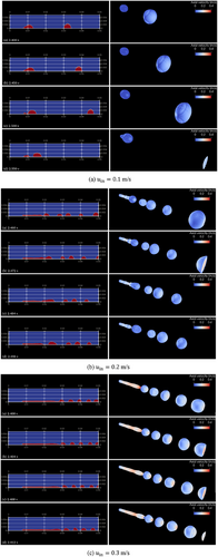
At uin = 0.2 m s−1, a liquid jet formed, with capillary waves developing on its surface due to Rayleigh instability. The waves amplified while advecting downstream, leading to periodic disintegration. However, breakup did not occur at regular intervals. Instead, it was influenced by the dynamic behavior of suspended droplets forming at the jet tip. These droplets repeatedly elongated and contracted due to surface tension, generating an adverse pressure gradient that disrupted the growth of Rayleigh instability and delayed breakup. As a result, the droplet size varied significantly, and the breakup was governed by the interplay of inertia, surface tension, and gravity rather than Rayleigh instability alone.
In contrast, at uin = 0.3 m s−1, the liquid jet fragmented stably, producing uniformly sized droplets. Although similar disturbances also occurred at the jet tip, the higher inertia of the liquid prevented the formation of suspended droplets with oscillatory behavior. The Rayleigh instability was able to develop without being disrupted, resulting in consistent breakup. This key difference emphasizes the decisive influence of injection velocity on the dominance of either surface-tension-driven oscillations or Rayleigh-instability-induced breakup. A similar uniform breakup was observed for uin = 0.4 m s−1, further reinforcing the trend.
3.1.2 Droplet Size
The mean droplet diameters for different injection velocities are shown in Fig. 4. The sphere-equivalent diameter was calculated based on the volume fraction-weighted sum of cell volumes. The numerical results matched experimental values across all cases, validating the simulations. However, under dripping conditions, the droplet diameter was slightly underestimated, likely due to neglecting nozzle geometry details, wall thickness, and material wettability, which affect droplet formation.

Tab. 5 presents droplet diameter variance. At uin = 0.2 m s−1, variance was relatively large, leading to non-uniform droplet generation, independent of the velocity distribution at the inflow boundary. Conversely, at uin = 0.3 −0.4 m s−1, droplets were uniform, with significantly lower variance. A previous study [1] reported that the most uniform droplets were obtained at uin = 0.37 m s−1, recommending it as an optimal condition for a spray tower. Our results support this conclusion, suggesting stable uniform droplet formation across different velocity profiles inside the nozzle.
| Injection velocity [m s−1] | Variance | |
|---|---|---|
| Laminar flow | Plug flow | |
| 0.05 | 2.88 × 10⁻¹¹ | 5.66 × 10⁻⁶ |
| 0.1 | 2.69 × 10⁻¹¹ | 1.19 × 10⁻¹⁰ |
| 0.2 | 2.01 × 10⁻⁷ | 1.15 × 10⁻⁷ |
| 0.3 | 4.57 × 10⁻¹⁰ | 1.64 × 10⁻⁷ |
| 0.4 | 1.02 × 10⁻⁹ | 2.07 × 10⁻¹¹ |
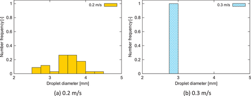
Fig. 5 shows droplet size distributions under a smooth jet regime with a developed laminar velocity profile at the nozzle exit. Data were sampled every 0.2 s from 2.0 to 6.0 s. A narrow droplet size distribution at uin = 0.3 m s−1 was attributed to periodic breakup. In contrast, a broader distribution at uin = 0.2 m s−1 suggests greater sensitivity to external disturbances, reinforcing the consistency between numerical and experimental findings (Fig. 3c).
3.2 Rotary Atomization Simulations
3.2.1 Trajectory of the Liquid Jet
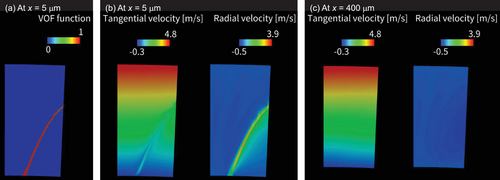
Fig. 6 illustrates the volume fraction and velocity distribution of a single liquid jet in Case InOutBC, providing insight into its trajectory under rotary atomization conditions. As the liquid jet was ejected from the rotating body, it initially extended smoothly before curving due to Coriolis force effects. In a stationary frame, a jet would need to rotate at the same angular velocity as the rotating body to travel in a straight line. However, in reality, air resistance caused a reduction in circumferential velocity at the jet tip, leading to a gradual misalignment with its base and resulting in the characteristic curvature. The cross-sectional view (Fig. 6b) confirms that Coriolis force enhances circumferential velocity while suppressing radial motion. Further downstream at x = 400 µm (Fig. 6c), the jet was sufficiently distant from the rotating body for airflow interactions to become negligible, highlighting how gas–liquid interactions are more dominant near the injection point.
The role of gas–liquid interactions was further explored by analyzing single and multiple jets (Fig. 7). Although three jets were introduced from different positions, their bases were aligned at θ = 0 for comparison. In Case PeriodicBC, all three jets followed nearly identical trajectories, indicating minimal influence from adjacent jets on either side. As a result, in Fig. 7, although three trajectories are plotted for PeriodicBC, they completely overlap and appear as a single line. Conversely, in Case InOutBC, the Triple-upstream jet exhibited significantly larger curvature, a result of stronger air resistance effects from the inflow boundary. The other two jets in the middle and downstream positions experienced different local airflow environments and followed slightly different paths. Thus, all three trajectories are distinguishable in Fig. 7 for InOutBC. Notably, the single jet trajectory in Case InOutBC closely resembled that of the Triple-upstream jet, confirming that upstream jet interactions substantially impact trajectory dynamics.
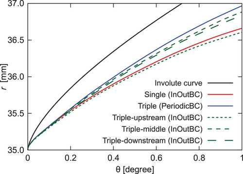
These findings highlight that as rotational speed increases, jet thickness decreases, intensifying gas–liquid interactions and further amplifying curvature effects. The results underscore the dominant influence of air resistance in dictating jet trajectory under rotary atomization, a phenomenon distinct from conventional linear jet behavior.
3.2.2 Atomization Characteristics
Fig. 8 illustrates the breakup dynamics of the liquid jet in rotary atomization, showing iso-surfaces of volume fraction (0.5). The jet elongated from the rotating body's edge, and as its diameter decreased, fragmentation occurred due to aerodynamic forces and surface tension effects. Unlike in linear jet configurations, rotary atomization induced localized oscillations and the formation of nodes along the jet. When a node swelled significantly, a necking region formed near the swollen area, where the local curvature increased. This led to enhanced surface tension effects in that narrow region, promoting pinching and droplet formation. Breakup was observed not only at the jet tip but also along its midsection, where surface wave instabilities triggered secondary fragmentation. Multiple breakup locations along a single jet led to the simultaneous generation of primary and satellite droplets.
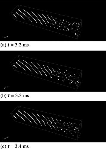
These observations indicate that breakup in rotary atomization is highly nonlinear and is governed by the competing effects of surface tension and aerodynamic disturbances, which together give rise to fluid instabilities. Although surface tension acts as a stabilizing force, aerodynamic forces amplify perturbations and promote instability. Traditional linear stability theory, which predicts perturbation growth in a uniform manner, fails to capture these complexities. Instead, this numerical simulation successfully reproduced the nonlinear interactions governing droplet formation, bringing it closer to experimentally observed behaviors.
Droplet size distribution was also analyzed (Fig. 9). Fig. 9a illustrates the method for identifying individual droplets based on their shape, with liquid structures that were elongated (such as pre-breakup ligaments) excluded from the analysis. Specifically, the equivalent spherical diameter was calculated from the total volume of each isolated liquid region using a volume-fraction-weighted integration. Droplets in contact with computational boundaries were also excluded to avoid partial data. Although the projected area was shown in Fig. 9a, it was used only for shape assessment and was not used to calculate the droplet diameter. Sampling was performed every 0.2 ms in the time interval from 3.5 to 5.5 ms. During this period, the same droplet might be counted multiple times, but this was considered acceptable given the transient nature of the atomization process and the statistical averaging applied over multiple time frames.
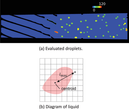
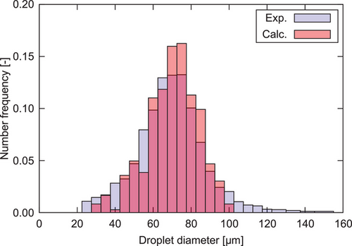
Fig. 10 compares numerical and experimental results [25], showing excellent agreement, particularly at 8000 rpm, where the liquid jet elongated and fragmented into smaller jets and droplets, progressively atomizing. These findings reinforce that gas–liquid interactions play a crucial role in dictating jet breakup under rotary atomization conditions. Moreover, the Coriolis and centrifugal forces governing jet curvature are fundamental to understanding breakup mechanisms. As a result, this study provides deeper insight into the physics of rotary atomization, offering a strong foundation for optimizing industrial spray processes.
4 Conclusion
This study investigated the breakup behavior of liquid jets in both linear and rotary atomization, focusing on the governing mechanisms. Using direct numerical simulations with the VOF method, the results highlighted the significant role of gas–liquid interactions in rotary atomization. The curvature of the liquid jet, driven by Coriolis and centrifugal forces, played a crucial role in determining breakup patterns, leading to the formation of both primary and satellite droplets. These patterns, influenced by surface tension, fluid instabilities, and aerodynamic disturbances, could not be fully explained by conventional linear stability theory, underscoring the need to account for nonlinear flow dynamics.
The numerical simulations successfully captured these nonlinear breakup behaviors, showing strong agreement with experimental droplet size distributions. The findings emphasize that gas–liquid interactions and jet curvature are fundamental in rotary atomization, shaping breakup dynamics in ways distinct from conventional linear jets. This study provides deeper insight into the complexity of droplet formation, reinforcing the importance of advanced numerical simulations for optimizing atomization processes.
Acknowledgments
During the preparation of this work, the authors used ChatGPT 4o in order to assist in drafting and refining the English text. After using this tool/service, the authors reviewed and edited the content as needed and take full responsibility for the content of the published article.


