First direct in vivo comparison of two commercially available three-dimensional quantitative coronary angiography systems
Abstract
Aim: The in vivo comparison of the accuracy of two 3-dimensional quantitative coronary angiography (QCA) systems. Methods: Precision-drilled plexiglass phantoms with five different luminal diameters (0.5–1.9 mm) were percutaneously inserted into the coronary arteries of four Yorkshire pigs. Twenty-one angiographic images of these stenotic phantoms were acquired for in vivo validation testing. Quantitative assessments of the minimum, maximum, and mean luminal diameters together with the minimum luminal area were determined using two 3D QCA systems, the CardiOp-B® and CAAS 5. Results: The CardiOp-B system significantly underestimated the minimum luminal diameter MLD whilst both systems significantly overestimated the maximum luminal diameter at the minimal luminal area (MLA) over the phantom's true value. The CAAS 5 system had a greater degree of accuracy/mm (mean difference = 0.01 vs. 0.03) and precision/mm (SD = 0.09 vs. 0.23) than the CardiOp-B in assessing the minimal LD. An increased precision/mm (SD = 0.01 vs. 0.29) and accuracy/mm (mean difference = 0.03 vs. 0.11) in the mean LD was observed with the CAAS 5. In comparing the MLA/mm2 the CAAS 5 was more precise/mm2 (SD = 0.14 vs. 0.55) and accurate/mm2 (mean difference = 0.12 vs. 0.02) to the true phantom MLA compared to the CardiOp-B system. Conclusions: In a 21 phantom study, the CAAS 5 3D QCA system had a greater degree of accuracy and precision in both the luminal and area measurements than the CardiOp-B 3D QCA system. © 2008 Wiley-Liss, Inc.
INTRODUCTION
In the percutaneous treatment of coronary artery disease the on-line two-dimensional quantitative angiography (QCA) is often the chosen method to determine both the vessel length and size to guide stent implantation [1]. There are, however, several limitations with this technique as depending on the angiographic views the vessels can appear foreshortened or overlapped resulting in inaccurate measurements [2]. Moreover, in tortuous vessels this can lead to an underestimation of the appropriate length of stent required to cover the lesion [3]. Recently, a novel method, the three-dimensional (3D) reconstruction of standard coronary angiography using an algorithm integrating single-plane images has been validated [4]. This technology is aimed at providing a solution to many of the limitations inherent with 2D-QCA. In addition, the enhanced accuracy in determining the lesion length and luminal diameter the 3D reconstructed image can be incorporated in a designated navigation software (Navigant® Stereotaxis, St Louis, MO) to enable magnetically aided guidewires to precisely transit through the vessel lumen [5]. The accuracy of the luminal diameter can be crucial for a successful wire transit to avoid vascular wall trauma or plaque disruption [6]. The potential benefits of this 3D-QCA technology has led two companies Paieon Medical, Rosh Ha'ayin, Israel and Pie Medical Imaging, Maastricht, the Netherlands to develop the CardiOp-B and CAAS 5 systems, respectively. Both systems are similar in using two angiographic images to reconstruct a 3D image but in the current version of the CardiOp-B the calibration standard is performed manually whilst in the CAAS 5 system it is automated. The aim of this study was to compare the accuracy of the detection of a luminal stenosis using two 3D QCA systems in vivo using radiolucent cylindrical plexiglass or polyamide stenotic phantoms with precision-drilled eccentric lumens implanted in porcine coronary arteries [7].
METHODS
The ethics committee on animal experimentation at the Erasmus Medical Center, Rotterdam, NL approved the study that was conducted in accordance to the guidelines of the American Heart Association on animal use in research.
Preparation and Insertion of the Stenotic Phantoms
The stenotic phantoms (Fig. 1) were precisely engineered by the Department of Bioengineering at the Erasmus Medical Center. Radiolucent plexiglass (acrylate) and polyacrylamide cylinders of diameters 3.0 or 3.5 mm and length of 8.28, 7.96, 7.85, 8.01, and 7.38 mm were precision-drilled to have circular lumens of 499 (aimed to be 0.5 mm), 707 (0.7 mm), 982 (1.0 mm), 1,367 (1.4 mm), and 1,921 (1.9 mm) μm in diameter, respectively. This accuracy calibrated optically at 40-fold magnification achieved a maximum tolerance of 0.003 mm. A second 1.3 mm diameter lumen was drilled parallel to the stenosis lumen to attach to the tip of 4-Fr Fogarty catheters (Vermed, Neuilly en Thelle, France) to facilitate the intracoronary insertion and positioning of the phantoms. Four Yorkshire pigs (average weight, 40–45 kg) were pretreated with intramuscular ketamine (20 mg/kg) and intravenous etomidate (5 mg/kg). The animals were then intubated and ventilated with a mixture of oxygen and isoflurane. Anesthesia was maintained with a continuous intravenous infusion of pentobarbital (5–20 mg/kg/hr). About 12-Fr introducer sheaths were inserted into both carotid arteries to allow the sequential insertion of the guiding catheter and the phantoms. Jugular access was used for the administration of medication and fluids. An intravenous bolus (10,000 IU/l) followed by a continuous infusion of heparin was given. Following the experiments, the animals were humanely euthanized.
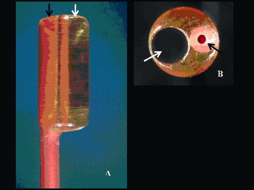
The magnified tip of one of the Fogarty catheters view along its long (A) and short axis (B) with a transparent radiolucent cylinder (phantom) having a channel of 1.9 mm diameter (white arrow) and the catheter lumen used for insertion of removable metallic stylet (black arrow) to aid positioning. [Color figure can be viewed in the online issue, which is available at www.interscience.wiley.com.]
In Vivo Image Acquisition of Stenosis Phantoms by Fluoroscopy
Biplane cine angiographic system (Axiom Artis™, Siemens, Forchheim, Germany) was used to create digital angiograms of matrix size of 1024 × 1024 pixels. Identical radiographic imaging settings were employed (kVp, mA, ms) in the two projections used to image each phantom to maintain consistency. Following intubation of the left or right coronary artery with a 6-Fr guiding catheter (Mach 1™, Boston Scientific, Natick, MA) intracoronary isosorbide-dinitrate (1 mg) was administered and an angiogram was made to aid orientation of the phantom in the vessel. The phantoms were wedged in the coronary arteries and positioned in the X-ray isocenter using the tip of a metal wire marker placed on the Fogarty catheter. Coronary angiography was performed by manual injection of contrast medium (Visipaque™ 320 mg I/ml, Amersham Health B.V., Eindhoven, The Netherlands). The ventilator was disconnected transiently during contrast injection to minimize the effect of diaphragmatic movement on angiographic images.
Three Dimensional QCA Analyses of In Vivo Phantom Images
In total, 21 readings were made in 21 different arteries; four arteries had phantoms of diameters 1.9 mm, six arteries had phantoms of 1.4 mm, six arteries had 1 mm diameter phantoms, four arteries had 0.7 mm phantoms, and one artery had a 0.5 mm phantom. The in vivo analysis of each phantom was performed in end-diastole on the same number of the frame count and was ECG gated so that all of the analyses using both QCA systems were performed on identical images. Calibration of the CardiOp-B system was done manually using the conventional catheter calibration of the nontapering part of the tip of each 6-Fr guiding catheter filled with contrast. The CAAS 5 system performs an automatic calibration based on the DICOM information in the image. Once calibrated, the two orthogonal views (at least 30° apart) that were simultaneously acquired in the biplane system were then used to reconstruct the 3D vessel image (Fig. 2). This was achieved by marking three points in the CardiOp-B system: proximally, distally, and at the stenosis on the two angiographic images. In the CAAS 5, this was done by defining a common image point (a landmark common to both images), and two points distal and proximal to the stenotic region [8]. The software then created automatic contour detection and if this was inaccurate then finer adjustments were made to the edge detection manually in the CardiOp-B system and the restriction option, an algorithm that excludes gross image artifacts such as the diagnostic catheter was applied in the CAAS 5 system. The restriction option is therefore not a manual edge correction but instead it offers users the possibility of excluding parts of the image of the detection by restricting the area of interest.
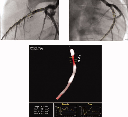
The 3D reconstruction of a phantom derived from two orthogonal views (frontal and lateral) using the CASS 5 system. The 3D color varies according to the severity of stenosis ranging from white (healthy vessel) to dark red (99% cross-sectional area stenosis). The yellow squares denote proximal reference point (P*), most stenotic point (S), and distal reference point (D) of the target lesion, respectively. The region of interest (ROI) for calculation of mean luminal diameter can be manually defined by moving the proximal (P*) and distal (D) points (Definition of ROI for mean LD; Graph view). [Color figure can be viewed in the online issue, which is available at www.interscience.wiley.com.]
Following contour detection and corrections/restrictions if required, the 3D reconstruction of the artery was automatically created. The software determined the minimum luminal area (MLA) and the pixel size at each position in the 3D space. Based on the position of the MLA and the known pixel size, the minimum luminal diameter (MLD) for each of the angiographic images was automatically calculated. Assuming a noncircular shape at the MLA then there will be two MLD values (maximum and minimum LD) obtained, the smallest representing the absolute MLD. The mean luminal diameter was based on the values in between the borders of a predetermined segment in the phantom (Fig. 2). Along the centerline in between this segment, the diameter at each scanline was taken and divided by the total number of scanlines to automatically afford the mean LD. The following data was therefore compared, the minimum LD (MLD) and the maximum LD at the MLA, together with the minimum luminal area MLA and the mean LD over the region of interest (ROI) in each 3D QCA system to that of the phantom models. We purposely chose to perform only one measurement per phantom given the primary interest in the relative accuracy and precision of both techniques, instead of an assessment of the intra- and inter-observer variability of the QCA techniques. Expert users from both the Pie Medical and Paieon companies were used to perform the measurements.
Statistical Analysis
Continuous variables are presented as mean ± standard deviation and compared using the Wilcoxon signed-rank test. Categorical variables are expressed as counts and percentages. The mean of the differences between measurements and phantom dimensions of both systems was computed and considered to be an index of the accuracy of the measurements, while the standard deviation of the differences was defined as an index of precision. Bland–Altman plots [9] were used to assess the agreement between both 3D QCA systems and the phantom models. Pearson's correlation was used to determine the degree of correlation between the measurements. Statistical analyses were performed with SPSS 12.0.1 for Windows (SPSS, Chicago, IL). A P value < 0.05 was considered statistically significant.
RESULTS
Comparison of Minimum LD with Phantom “True” Values
In this study the CardiOp-B system had only one manual adjustment to correct the detected contour whilst six adjustments were used in the CAAS 5 system to restrict the contours to the region of interest. Overall, the comparison of both 3 D QCA systems with the true LD noted in the 21 phantom models revealed a closer association with the CAAS 5 system than in the CardiOp-B (Table I). The CardiOp-B system significantly underestimated the minimum LD (MLD) whilst both systems significantly overestimated the maximum LD at the MLA over the true value. In assessing the MLD, the CAAS 5 system had a greater degree of accuracy/mm (mean difference = 0.01 vs. 0.03) and precision/mm (SD = 0.09 vs. 0.23) compared with that observed with the CardiOp-B system. The Bland–Altman plots of the MLD (Fig. 3a and b) showed that both systems had one outlier reading beyond 2 SD. This value was, however, smaller in the CAAS 5 system resulting in a better overall correlation to that of the phantom's actual diameter (r = 0.99 vs. 0.87) and influencing the degree of precision. Notably, in the CardiOp-B system 11/21 (52%) of the measurements laid outside ± 10% of the true phantom LD compared with 3/21 (14%) of the measurements derived using the CAAS 5 system. Table I and Fig. 3a and b compares min LD (MLD) in both systems.
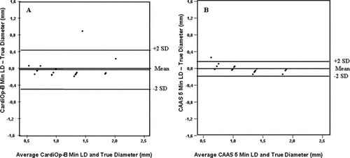
Bland–Altman plots of the minimal LD (a) CardiOp-B® with the phantoms (b) CAAS 5 with the phantoms.
| Accuracy | Precision | Correlation | Slope | Intercept | P value | |
|---|---|---|---|---|---|---|
| CardiOp-B® vs. phantoms | ||||||
| Min LD (MLD) | 0.03 | 0.23 | 0.87 | 0.87 | 0.15 | 0.03 |
| Max LD | 0.24 | 0.40 | 0.78 | 0.86 | 0.23 | 0.001 |
| Mean LD | 0.11 | 0.29 | 0.84 | 1.02 | 0.08 | 0.31 |
| MLA | 0.12 | 0.55 | 0.87 | 1.09 | 0.01 | 0.74 |
| CAAS 5 vs. phantoms | ||||||
| Min LD (MLD) | 0.01 | 0.09 | 0.99 | 0.92 | 0.06 | 0.26 |
| Max LD | 0.06 | 0.11 | 0.97 | 1.12 | 0.10 | 0.015 |
| Mean LD | 0.03 | 0.10 | 0.98 | 0.87 | 0.19 | 0.39 |
| MLA | 0.02 | 0.14 | 0.99 | 0.91 | 0.13 | 0.95 |
- Accuracy = mean differences between recorded measurements and the phantom; Precision = standard deviation and P value is derived from the recorded measurements and the phantom.
Comparison of Mean LD with Phantom “True” Values
There was no significant difference observed when the mean LD in either system was compared with the luminal diameter of the phantoms (Table I). The Bland–Altman plots revealed two observations outside ± 2 SD range in the CardiOp-B analysis compared with only one observation noted in the CAAS 5 system (Fig. 4a and b). As observed with the minimum LD values there was an increased precision/mm (SD = 0.10 vs. 0.29) and accuracy/mm (mean difference = 0.03 vs. 0.11) with the CAAS 5 mean LD values with the latter having a closer correlation with the true value (r = 0.98 vs. 0.84). Figure 4a and b compares mean LD in both systems.
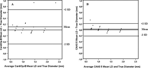
Bland–Altman plots of the MLD (a) CardiOp-B® with the phantoms (b) CAAS 5 with the phantoms.
Comparison of Minimal Luminal Area with Phantom “True” Values
The Bland–Altman plots of the MLA further demonstrated higher precision/mm2 (SD = 0.14 vs. 0.55) and accuracy/mm2 (mean difference = 0.02 vs. 0.12) with the CAAS 5 (Fig. 5a and b). Moreover, in the CardiOp-B system 14/21 (67%) of the measurements laid outside ± 10% of the true phantom MLA compared with 7/21 (33%) of the measurements derived using the CAAS 5 system. Consequently, the Pearson coefficient demonstrated a closer correlation with the CAAS 5 than the CardiOp-B system (r = 0.99 vs. 0.87). Figure 5a and b compares mean LD in both systems.
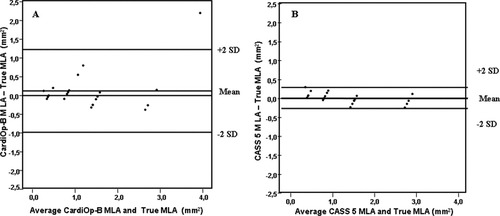
Bland–Altman plots of the MLA (a) CardiOp-B® with the phantoms (b) CAAS 5 with the phantoms.
DISCUSSION
3D QCA has been shown in phantom models [10] as well as in stented vessel segments [11], and complex lesions like bifurcations [12] to have a closer correlation to the true vessel's dimensions than 2D QCA. Moreover in conventional angiography, overlapping vessel can impair the optimal visualization of a lesion and if the lesion is eccentric then it may be missed altogether [13]. In the formulation of a 3D QCA, the system uses a 3D computer-based modelling algorithm to integrate the 2D projections, identify key vessel features like bifurcations and the centreline, calculate and display the vessel's cross-sectional contours that are subsequently “filled in” to create the virtual vessel. Both the CardiOp-B system and CAAS 5 systems adopts this system when generating the reconstructed vessel but there are subtle differences between the two program that may influence the degree of accuracy. The CardiOp-B system utilizes a manual guide catheter mode calibration method in contrast to the CAAS 5 system that uses an automatic calibration at the region of interest (ROI). With the manual method, the catheter size in French or mm has to be inputted for system recognition and calibration. This is an established method that has been shown to have greater precision than the equivalent 2D measurements with respect to the minimal lesion diameter (P < 0.005), minimal lesion area (P < 0.05), and lesion length (P < 0.01) [4]. However, it has been reported that because the catheter may not be in the same plane as the ROI that this method of calibration can give rise to differences in magnification and measurements and influence the accuracy [13]. In addition, the way in which the contour is drawn on the 2D angiographic image also highlights an important difference that may also influence the accuracy and precision between the two systems. Both the CardiOp-B and CAAS 5 systems have the ability to manually correct the generated contours if they are adjudged to be inaccurate. Although this is subjective, in this paired comparative study contour adjustment had to be performed on one of the 21 phantom models in the CardiOpB as the detected contour deviated significantly from the vessel's edge. In the rest of the models, edge detection was adjudged satisfactory. No edge corrections were needed in the CAAS 5 but the catheter had to be excluded from the ROI on six occasions. Because the edge detection is used to deduce the measurement, the less manual correction needed then greater is the accuracy of the automated system.
The aim of this study was to evaluate the accuracy and precision of both the CAAS 5 and CardiOp-B 3D QCA system with respect to precisely engineered stenotic phantoms in vivo. The rational was that in addition to evaluating precision in measurements, the importance of the study stems from the demand to accurately determine the luminal diameter so that a precise endoluminal road map of a vessel can be achieved for magnetic navigation when the 3D reconstructed image is incorporated in the Navigant software [14]. The lack of accuracy may result in the guidewire exiting from the vessel lumen to cause a perforation. The results demonstrated good overall correlation of the minimal LD and maximum LD at the MLA together with the mean LD and MLA in each system to the true values of the phantoms. However in the CardiOp-B system, the range of these correlations were slightly less (0.78–0.87) compared with the CAAS 5 system (0.97–0.99). In addition, systematic underestimation of luminal diameter measurements has been previously reported for the CardiOp-B system QCA system [11]. In assessing the minimum LD (MLD), greater precision and accuracy was observed with the CAAS 5 arguably because of two observations in the CardiOp-B system varying markedly from the true value (Δ min LD 47% and 25%) in comparison to one observation (Δ min LD 34%) in the CAAS 5 system. However, what is important to note is that in terms of the accuracy is that 11/21 (52%) of the measurements laid outside ± 10% of the true phantom LD using the CardiOp-B system compared with 3/21 (14%) of the measurements derived using the CAAS 5 system. This was also mirrored with the MLA measurements where two thirds of the values in the CardiOp-B system 14/21 laid outside ± 10% of the true phantom MLA compared with one third (7/21) with the CAAS 5 system. The result highlights the perceived superiority of automatic isocenter calibration together with improved edge detection [15].
Despite the variability in 3D QCA measurements in both systems, we should remain appreciative of the fact that this novel technology creates a 3-dimensional coronary map and as such have widespread application to both scientific research and clinical practice. By doing so, it solves many of the limitations currently observed with 2D QCA and unlike other imaging modalities like multislice computed tomography and magnetic resonance imaging it can provide absolute measurements of coronary luminal diameter and lengths in real time. It is therefore hopeful that the findings of our study will stimulate further research in this exciting new imaging field.
LIMITATIONS
This study is the first direct comparison of two commercially available 3D QCA systems. The study was, however, limited by the relatively small sample size of 21 phantom models. This was due to difficulties in obtaining more animal models. The concentric phantoms used in this study do not represent natural coronary lesions, as they do not allow the assessment of asymmetry. It is better to use eccentric phantoms but precise and validated eccentric phantoms were not available. The validation tests with these cylindrical concentric phantoms were, however, used by our group recently to test 2D and 3D QCA systems [10].
CONCLUSION
In a 21 phantom study, the CAAS 5 3-D QCA system had a greater degree of accuracy and precision in both the luminal and area measurements than the CardiOp-B 3D QCA system. Further development and validation studies are warranted in order for this novel technology to be increasingly adopted in routine clinical practice.
Acknowledgements
The authors thank Avital Forsher and Vera Nyssen for performing the analyses.


