Safety assessment of ultra-wideband antennas for microwave breast imaging
Abstract
This article deals with the safety assessment of several ultra-wideband (UWB) antenna designs for use in prototype microwave breast imaging systems. First, the performances of the antennas are validated by comparison of measured and simulated data collected for a simple test case. An efficient approach to estimating the specific energy absorption (SA) is introduced and validated. Next, SA produced by the UWB antennas inside more realistic breast models is computed. In particular, the power levels and pulse repetition periods adopted for the SA evaluation follow the measurement protocol employed by a tissue sensing adaptive radar (TSAR) prototype system. Results indicate that the SA for the antennas examined is below limits prescribed in standards for exposure of the general population; however, the difficulties inherent in applying such standards to UWB exposures are discussed. The results also suggest that effective tools for the rapid evaluation of new sensors have been developed. Bioelectromagnetics 33:215–225, 2012. © 2011 Wiley Periodicals, Inc.
INTRODUCTION
Recently, radar-based microwave imaging has been proposed as a promising alternative for early-stage breast cancer detection [Fear, 2005; Li et al., 2005; Kosmas and Rappaport, 2006; Klemm et al., 2007]. Unlike X-ray mammography, ultrasound, and magnetic resonance (MR) imaging, this technique typically involves illuminating the breast with a series of pulses as an antenna is scanned around the breast. The signal utilized is ultra-wideband (UWB) in frequency, resulting from a compromise between resolution, attenuation, and sensor performance at low frequencies. The relative arrival times and amplitudes of the backscattered signals provide information that is used to determine the scatterer (tumor) location using robust synthetic focusing algorithms [Fear, 2005; Li et al., 2005; Kosmas and Rappaport, 2006; Klemm et al., 2007].
While the signals utilized in the UWB microwave imaging scan are expected to be low power, safety assessment is important prior to scanning volunteers and patients. The risk assessment of any electrical devices emitting electromagnetic (EM) energy is regulated by standards issued by technical organizations and governments (e.g., the International Commission on Non-Ionizing Radiation Protection (ICNIRP) and the Institute of Electrical and Electronics Engineers (IEEE)). These standards do not apply to medical devices, however, comparison of the exposure during a microwave breast imaging scan to limits prescribed by safety standards provides an initial assessment. Moreover, the safety assessment may also be used in the future to guide selection of power levels, number of transmitted pulses, and/or scan locations.
In this article, we evaluate the safety of several UWB antenna designs for microwave breast imaging. The antennas and the measurement protocol examined are used with the tissue sensing adaptive radar (TSAR) system. TSAR is a monostatic radar-based approach to microwave breast imaging. Safety evaluation of the TSAR system has been required as part of initial testing on humans [Sill et al., 2011]. Despite the focus on a particular system, this study is expected to provide insights useful for other microwave imaging systems. For example, the three antennas investigated include a balanced antipodal Vivaldi antenna (BAVA), a modified BAVA with enhanced directivity (BAVA-D), and a novel antenna (Cassiopeia) that is designed to operate independent of immersion liquid and in contact with the breast. These antennas permit us to explore absorption of microwave energy in a variety of practical scenarios, providing insight into whether this quantity changes significantly with antenna design and location. We also developed a realistic breast model based on a MR scan of a patient, and a simple cylindrical breast model that permits us to predict “worst-case” absorptions for a selected sensor. This model is independent of variations in breast shape, size, and tissue distributions found in patient-specific breast models.
Safety Assessment of UWB Exposures
The sensors used for microwave breast imaging are typically placed close to the breast, necessitating calculation of energy absorptions inside the breast. However, due to the pulsed nature of UWB technology, this calculation and comparison with safety limits is complicated.
Firstly, there are only a few reports (to the knowledge of the authors) pertaining to UWB exposures. The safety assessment of UWB radio systems for body area network (BAN) applications was investigated by Wang and Wang [2008] and De Santis et al. [2010]. Also, two reports dealt specifically with UWB exposures expected during microwave breast imaging [Zastrow et al., 2006, 2007]. Both articles numerically analyzed realistic models of the breast when illuminated with a ridged pyramidal horn antenna purposely designed for breast imaging. The first article describes the safety assessment at selected frequencies [Zastrow et al., 2006], while a time-domain approach is discussed by Zastrow et al. [2007]. As these reports are specific to a particular antenna, there is a need for safety evaluation of other designs proposed for microwave breast imaging application.
Secondly, the ICNIRP and IEEE C95.1 safety standards [ICNIRP, 1998; IEEE Std C95.1, 2006] are not clear on exposure to UWB fields. Indeed, at microwave frequencies, the most effective dosimetric quantity adopted by such standards is the specific absorption rate (SAR). The limits on SAR are established to prevent heating effects. However, this basic restriction is meaningful only for time-harmonic fields. For pulsed fields, exposure limits are instead given in terms of specific absorption (SA) to prevent the microwave hearing effect, and temporal peak of the in situ electric field to prevent electrostimulations. Nevertheless, in the opinion of the authors, both pulsed restrictions are not easily applied to microwave breast imaging exposures since the first effect concerns localized head exposures, while the second effect occurs at low frequencies. Therefore, for UWB microwave breast imaging, it is not clear which is the most meaningful dosimetric quantity. The SA is likely an appropriate and effective measure, however, the SA limits to be adopted by safety standards differ in terms of averaging time. Specifically, a peak value of 28.8 J/kg averaged over 10 g should never be exceeded over any one-tenth second period [IEEE Std C95.1, 2006]. It is worthy noting that such a value is derived from maximum permissible exposure referred to whole-body occupational exposures (i.e., 0.4 W/kg) and therefore a higher value of 144 J/kg should be applied when considering localized exposures for general public (i.e., 2 W/kg). A value of 2 mJ/kg averaged over 10 g is instead specified for the general public by the ICNIRP [1998] safety guideline. In this case, the averaging time is not clearly specified (see Table 4, note 7 in ICNIRP [1998]). However, it is explicitly claimed that microwave hearing occurs for pulses of duration less than 30 {micro}s and therefore it is reasonable to consider the same order of magnitude for the SA averaging time.
Finally, a further critical issue concerns the fact that microwave breast imaging systems are still in a prototypal phase. This means that, for practical reasons, a multi-frequency vector network analyzer (VNA) is typically used to collect measurements. The breast is illuminated by sweeping over a frequency range and collecting measurements at selected frequencies, rather than by direct time-domain measurements of a UWB pulse. Thus, the time-domain SA evaluation employed by Zastrow et al. [2007], Wang and Wang [2008], and De Santis et al. [2010] cannot be applied here. Therefore, a novel frequency-domain SA evaluation approach starting from the SAR values obtained at different frequencies is proposed in this article.
MATERIALS AND METHODS
Antenna Models
We have developed three different antennas for use in prototype microwave breast imaging systems at the University of Calgary, Alberta, Canada (Fig. 1). The first two sensors are based on the well-known BAVA. Both Vivaldi antennas have been designed to operate over the frequency range from 2 to 12 GHz, although measurements may occur over a wider frequency range. The antennas are placed at a distance of 1 cm from the breast, and in an immersion liquid of canola oil. The canola oil permits reduction of both the sensor size and reflection from the skin when compared to free space. The second BAVA includes a dielectric director (BAVA-D), which is a novel feature introduced to additionally focus the near-field radiation in the endfire direction. Both versions of the antenna are thoroughly described in Bourqui et al. [2010b].
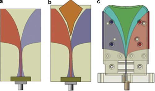
Proposed antennas used during a TSAR scan. a: BAVA. b: BAVA-D. c: Cassiopeia. [Color figure can be seen in the online version of this article, available at http://wileyonlinelibrary.com/journal/bem]
The third antenna is a tapered slot antenna fed by a transverse microstrip balun and it also includes a dielectric director. This antenna is termed the Cassiopeia antenna. The Cassiopeia antenna is designed to come in contact with the breast skin, and also to operate in a variety of immersion media (i.e., relatively independent of immersion medium). The antenna reported in this article is tested in an immersion liquid of pure glycerin. A detailed description of the Cassiopeia antenna is provided in Bourqui et al. [2010a].
Breast Model
- (1)
Simplified breast model: The simplified breast model consists of a 10 cm diameter and 10 cm long cylinder surrounded by a 2 mm layer of skin. The inside of the cylinder is filled with a homogenous material representing one of the three tissue groups defined in Lazebnik et al. [2007a]. These materials are referred to as Groups 1, 2, and 3. The aim of the simplified cylindrical model is to provide a conservative and “standard” testbed for SA/SAR evaluation. The cylindrical model removes the dependence of SA/SAR on the different shapes, sizes, and tissue distributions found in patient-specific models [Zastrow et al., 2007]. In addition, the simple model permits examination of the effect of various interior electrical properties, that is, the three different groups defined by Lazebnik et al. [2007a]. This allows us to select an interior tissue model that provides a best- or worst-case SA/SAR estimate.
- (2)
Realistic breast model: The realistic breast model is created from a set of MR images. The images are acquired in the sagittal plane with a VIBE sequence (a fat suppression technique that decreases the intensity of the fat so that the remaining tissues have a higher intensity) using a breast coil to enhance the images. The MR images have voxel size of 0.429 mm × 0.429 mm × 1.2 mm. The images are preprocessed to remove contrast gradients introduced by the MR breast coils and background noise. The preprocessed images are segmented using the commercial segmentation software tool, iSEG (Schmid & Partner Engineering AG (SPEAG), Zurich, Switzerland). A 2.145 mm layer of skin is added to the breast. The interior tissues are defined by applying a k-means filter, which is used to select regions of similar pixel intensity [Sill et al., 2011]. The number of tissues varies depending on the breast model. In the proposed article, we considered a 16-tissue breast model. The realistic breast has maximum cross-section dimensions of 13.5 cm × 15 cm and an extent of 10 cm, which is larger than the respective cylindrical model.

Breast models. a: Cylindrical model with Cassiopeia antenna. b: MR-based model with BAVA-D antenna. [Color figure can be seen in the online version of this article, available at http://wileyonlinelibrary.com/journal/bem]
EM Numerical Modeling
All the simulations are performed with the finite-difference time-domain (FDTD) technique using the commercial software tool, SEMCAD X (SPEAG). The several combinations of antennas and breast models are excited by a modulated Gaussian pulse with frequencies in the range of 1–15 GHz, which is the typical frequency band for radar-based microwave imaging techniques.
Following the experimental procedure, the BAVA and BAVA-D antennas are placed 1 cm from the breast (metallization end as reference), while the Cassiopeia is in contact with the breast model (Fig. 2). Moreover, the breast models illuminated by Vivaldi antennas are placed in canola oil, while those using the Cassiopeia antenna are placed in pure glycerine. The computational domain is truncated by perfectly matched layers (PMLs) [Bérenger, 2003].
Finally, the tissue dielectric properties are represented by Debye dispersion models in order to account for the frequency dependence inherent in UWB pulse propagation. Indeed, the simple Debye model represents a fair approximation of the more complex Cole–Cole dispersive model in the limited frequency range of 1–15 GHz [Lazebnik et al., 2007b]. Table 1 summarizes the Debye parameters for the cylindrical model. In particular, dielectric properties of the skin are obtained from Gabriel [1996], while those of the homogenous interior tissue are from Lazebnik et al. [2007a, b]. The dielectric properties of the 16-tissue realistic breast model are assigned electrical properties based on Lazebnik et al. [2007a, b] by mapping the pixel intensity to the electrical properties. In particular, a histogram of the breast model is created prior to segmentation. Then, it is determined that voxels with <30% of the maximum pixel intensity are considered fatty tissue, while those greater than 85% of the maximum pixel intensity are considered glandular tissue. The voxels that are related to the remaining pixels are termed transition regions. These tissue types correspond to the general groups defined in Lazebnik et al. [2007a]. For each tissue type, the segmented regions are mapped to the properties in the 25th and 75th percentiles for each tissue that is defined in Lazebnik et al. [2007a]. It should be noted that the average dielectric properties of the interior tissues of the real breast model are close to those of the cylindrical model with Group 2 material assigned to the interior.
| Tissue | εs | ε∞ | σ (S/m) | τ (ps) |
|---|---|---|---|---|
| Skin | 37 | 4 | 1.1 | 7.2 |
| Breast interior (Group 1) | 47.62 | 7.28 | 0.71 | 10.28 |
| Breast interior (Group 2) | 37.65 | 5.57 | 0.52 | 8.68 |
| Breast interior (Group 3) | 4.74 | 3.14 | 0.036 | 13.56 |
Safety Assessment
Antenna Validation Method
As a first step, we measure and simulate SAR for each of the antennas of interest in a simple scenario and at a single frequency. This configuration is aimed at ensuring that measurements and simulations for each antenna are in agreement in order to validate the adopted radiating system.
To assess the antennas, a custom phantom setup has been implemented, as shown in Figure 3. The setup includes a 45.7 cm diameter cylindrical tank filled with canola oil. The antenna of interest is placed at the center of the bottom of the tank, pointing up. At the tip of the antenna is a square box filled with a head-simulating liquid (HSL) used to mimic the electrical properties of the head at 2.45 GHz (i.e., εr = 36.7 and σ = 1.89 S/m).
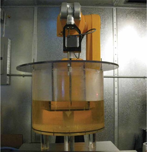
DASY4 measurement setup. [Color figure can be seen in the online version of this article, available at http://wileyonlinelibrary.com/journal/bem]
Measurements are performed with a DASY4 professional system (SPEAG), which is normally used in SAR measurements for compliance testing. The DASY system has an E-field probe that is used to measure the electric field inside the box of HSL by scanning the probe through a region of interest. The measurement protocol used with the DASY system follows the recommendations of the IEEE Std C95.3 [2002].
 (1)
(1)TSAR scan method
The prototype TSAR system uses a VNA (8722 ES, Agilent Technologies, Palo Alto, CA) to perform the breast scan. In particular, the frequency band of interest (1–15 GHz) is measured at 1601 frequency points over a 1.8 s sweep time. This corresponds to 1.124 ms illumination at each frequency. For one antenna location, this measurement is repeated three times and the data are then averaged. Therefore, the breast is illuminated for 3.372 ms at each measurement frequency. Then, the measurements are repeated as the antenna is scanned to 200 antenna positions (around the breast); the time to complete a scan is 30 min. The actual maximum leveled power that the VNA transmits is −5 dBm (or 0.32 mW), although higher power could be envisioned in the future.
SA evaluation method
 (2)
(2) (3)
(3)In this case, a broadband signal excitation with limited time duration (i.e., on the order of nanoseconds) can be used to extract the SAR values at selected frequency points. For practical reasons, the SAR produced by the several antennas inside a selected breast model is numerically evaluated at only a few frequency points (e.g., every 1 GHz). After that, the data are interpolated to account for the missing SAR values (the frequencies at which measurements are collected) and normalized to a power of −5 dBm. The SAR values are then multiplied by the time that each frequency is radiated during a sweep (i.e., Ti = 3.372 ms). By summing the contribution at each frequency point, one obtains the SA per sweep. Finally, by knowing the number of sweeps that are performed for a given time, one can extrapolate the total SA resulting from a 6 min exposure or a complete TSAR scan (i.e., 30 min). Specifically, 120 sweeps are performed in 6 min while a total TSAR scan takes 600 sweeps. A validation of the proposed technique, together with a sensitivity analysis on the interpolation effect, is reported in the following section.
RESULTS
Antenna Validation
To examine the results of measurements and simulations at a single frequency we present the SAR values, which include the 10 g and unaveraged peak SAR values. The measurement and simulation results in Table 2 show that the SAR values for measurements and simulations are in good agreement. We note that the BAVA-D values are smaller than the values for the BAVA due to differences in antenna positioning. For the BAVA, the antenna is positioned so the end of the metallization is 1 cm from the box of HSL. With the BAVA-D, the antenna is positioned so the end of the director is 1 cm from the box. Therefore, the aperture (end of metallization) of the BAVA-D is located further from the HSL than the BAVA, resulting in smaller values.
| Antenna | Peak SAR (W/kg) | Peak 10 g SAR (W/kg) | ||
|---|---|---|---|---|
| Measured | Simulated | Measured | Simulated | |
| BAVA | 0.043 | 0.045 | 0.020 | 0.021 |
| BAVA-D | 0.026 | 0.030 | 0.014 | 0.015 |
| Cassiopeia | 0.125 | 0.121 | 0.054 | 0.050 |
These results demonstrate that our measurements and simulations are in agreement at a single frequency of 2.45 GHz. Figure 4 compares simulated and measured reflection coefficients for the three antennas, suggesting that we can extend the validity of the radiating system over the frequency range of interest.
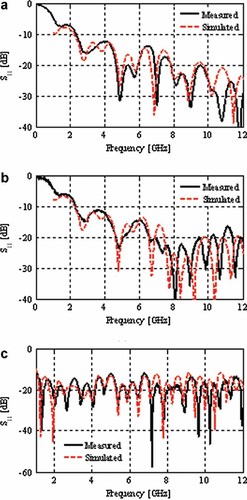
Measured and simulated reflection coefficient of the (a) BAVA, (b) BAVA-D, and (c) Cassiopeia in their respective immersion media, free of any backscattering sources. [Color figure can be seen in the online version of this article, available at http://wileyonlinelibrary.com/journal/bem]
SA Validation
To validate the proposed SA frequency-domain approach, a simple test case is considered, as shown in Figure 5a. It consists of a homogenous cubic tissue with Debye parameters (εs = 56, ε∞ = 26, σ = 0.64 S/m, and τ = 0.17 ns) excited by a plane wave with two different chirped signals (Fig. 5b). The first signal (called s1) is a three-tone harmonic signal with frequencies f1 = 0.6 GHz, f2 = 0.7 GHz, and f3 = 0.8 GHz, while the second chirped signal (called s2) has frequencies at f1 = 3 GHz, f2 = 4 GHz, and f3 = 5 GHz. Both signals have the same time duration Tmax = 3 ns with a constant single-tone time window of Ti = 1 ns. The SA produced inside the cubic tissue along the x-axis is shown in Figure 6 for both time- and frequency-domain approaches. As can be observed, the correlation is quite poor for the first chirped signal (average error of 20%), while good agreement is obtained for the second signal (average error of 5%). This means that Equation (3) is valid only when the considered harmonic tone fi has an even number of cycles (or reaches steady-state) within the considered time window Ti. It can be concluded that the adopted approach is consistent for TSAR safety assessments due to the long sweep time compared to the high involved frequencies. Indeed, even for the minimum illuminating frequency of 1 GHz, Ti is on the order of milliseconds and therefore the steady-state is always satisfied.

SA validation test case. a: Geometry configuration. b: Excitation signals. [Color figure can be seen in the online version of this article, available at http://wileyonlinelibrary.com/journal/bem]
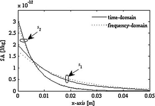
Comparison between the time-domain and frequency-domain SA evaluation.
TSAR Exposure
As previously described, the SA is obtained by means of a frequency-domain procedure starting from the SAR values evaluated at different frequencies. For the sake of completeness, first the SAR distribution at selected frequencies is illustrated. Then, the effect of the SAR interpolation on the SA evaluation is investigated. Figure 7 shows the SAR distribution (unaveraged) produced by the BAVA antenna inside the cylinder breast model (filled with material representing Group 1) at four selected frequencies when adopting a power output of −5 dBm at each frequency. In order to highlight this absorption effect and improve the picture readability, the SAR distributions are represented in a logarithmic scale by normalizing the maximum value (0.0625 W/kg) to 0 dB. From this figure it is evident that the skin depth phenomena lead to a stronger but superficial absorption as the frequency increases. The analysis of the interpolation effect is reported in Figure 8, where the SA maps (unaveraged and logarithmic scale) obtained inside the realistic breast model when illuminated by the BAVA antenna are shown for different numbers of extracted frequency points N. Specifically, the SAR values were extracted at frequencies fi = 1, 5, 10, 15 GHz for N = 4 (Fig. 8a); fi = 1, 2, … , 14, 15 GHz for N = 15 (Fig. 8b); and fi = 1, 1.5, 2, … ,14, 14.5, 15 GHz for N = 29 (Fig. 8c). Directly following the TSAR measurement procedure and extracting the SAR values at 1601 frequency points is computationally intensive and not practical. Although N = 4 appears to be an insufficient number of frequency points, the distributions at N = 15 and N = 29 are similar and the difference in the SA values is <2%. This suggests extracting the SAR values at only 15 frequency points and interpolating the remaining 1586 points, as shown in Figure 8d. In the following, all the SA results have therefore been evaluated by means of this interpolation procedure, representing a good trade-off between accuracy and computational cost.
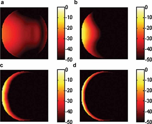
Unaveraged SAR distribution along the center slice of the cylinder breast model (Group 1) for the BAVA antenna at (a) 1 GHz, (b) 5 GHz, (c) 10 GHz, and (d) 15 GHz. SAR in dB normalized to 0.0625 W/kg. [Color figure can be seen in the online version of this article, available at http://wileyonlinelibrary.com/journal/bem]
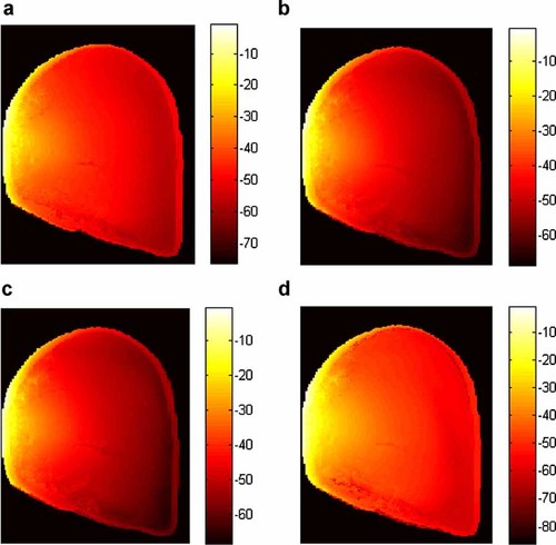
Unaveraged SA distribution along the center slice of the realistic breast model for the BAVA antenna. a: SA in dB normalized to 0.0567 J/kg for N = 4. b: SA in dB normalized to 0.0498 J/kg for N = 15. c: SA in dB normalized to 0.0505 J/kg for N = 29. d: SA in dB normalized to 0.0447 J/kg for N = 1601 (interpolated). [Color figure can be seen in the online version of this article, available at http://wileyonlinelibrary.com/journal/bem]
The SA distributions (unaveraged and logarithmic scale) obtained inside the realistic breast model for the three antennas resulting from exposure to a single VNA sweep are reported in Figure 9. As expected, the peak SA is concentrated close to the skin due to the high conductivity of this layer and the relatively high frequency involved. When comparing the BAVA and BAVA-D results, increased concentration of the distribution is noted for the BAVA-D, consistent with the increased focus of the fields due to the director. With the Cassiopeia, greater penetration of the fields is evident due to the contact between this antenna and the breast.
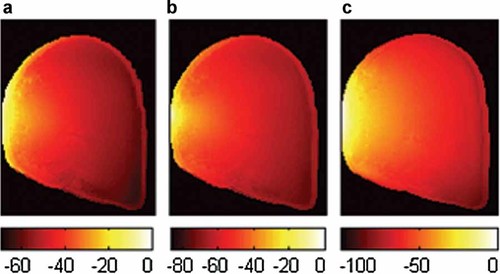
Unaveraged SA distribution along the center slice of the realistic breast model for the three antennas. a: SA in dB normalized to 0.0447 J/kg for the BAVA antenna. b: SA in dB normalized to 0.49 J/kg for the BAVA-D antenna. c: SA in dB normalized to 0.394 J/kg for the Cassiopeia antenna. [Color figure can be seen in the online version of this article, available at http://wileyonlinelibrary.com/journal/bem]
In addition to the SA/SAR distributions, it is relevant to quantify the absorptions and compare them with safety limits. The results of our investigation are therefore summarized in Tables 3 and 4. In particular, the specific absorptions obtained inside the breast models after exposure to a single sweep by the several UWB antennas are listed in Table 3, together with the SAR values at selected frequencies. The SA extrapolation after a 6 min exposure and a total TSAR scan are reported in Table 4 for the realistic MR breast model. It should be noted that these last values are overestimated since different regions of the breast are illuminated as the antenna location varies during the image scan; in turn, the SA peak location also changes position. Thus, multiplying the single SA per sweep by the number of sweeps performed within a specified time window represents the worst-case scenario of a fixed antenna illuminating the breast.
| Antenna | Breast model | 10 g SAR at 1 GHz (W/kg) | 10 g SAR at 5 GHz (W/kg) | 10 g SAR at 10 GHz (W/kg) | 10 g SAR at 15 GHz (W/kg) | 10 g SA at 1.8 s (J/kg) |
|---|---|---|---|---|---|---|
| BAVA | Cylinder Group 1 | 0.00013 | 0.00176 | 0.00194 | 0.00164 | 0.0025 |
| Cylinder Group 2 | 0.00012 | 0.00169 | 0.00177 | 0.00160 | 0.0024 | |
| Cylinder Group 3 | 0.00006 | 0.00084 | 0.00131 | 0.00118 | 0.0017 | |
| MRI realistic breast | 0.00014 | 0.00159 | 0.00174 | 0.00174 | 0.0024 | |
| BAVA-D | Cylinder Group 1 | 0.00013 | 0.00367 | 0.00870 | 0.00628 | 0.0073 |
| Cylinder Group 2 | 0.00012 | 0.00361 | 0.00847 | 0.00606 | 0.0071 | |
| Cylinder Group 3 | 0.00008 | 0.00222 | 0.00700 | 0.00571 | 0.0056 | |
| MRI realistic breast | 0.00015 | 0.00385 | 0.00844 | 0.00605 | 0.0072 | |
| Cassiopeia | Cylinder Group 1 | 0.00012 | 0.00500 | 0.00842 | 0.00733 | 0.0099 |
| Cylinder Group 2 | 0.00011 | 0.00486 | 0.00731 | 0.00690 | 0.0090 | |
| Cylinder Group 3 | 0.00013 | 0.00189 | 0.00650 | 0.00549 | 0.0077 | |
| MRI realistic breast | 0.00014 | 0.00387 | 0.00565 | 0.00420 | 0.0083 |
| Antenna | 10 g SA at 6-min (J/kg) | 10 g SA at TSAR scan (J/kg) |
|---|---|---|
| BAVA | 0.288 | 1.441 |
| BAVA-D | 0.885 | 4.423 |
| Cassiopeia | 1.001 | 5.005 |
The analysis of the obtained results indicates that the highest absorptions are obtained for the Cassiopeia antenna (since it is in contact with the breast). The BAVA-D results are very similar to the Cassiopeia due to the focusing effect of the director in the BAVA-D. For the realistic breast models, the 10 g SA values for the BAVA and BAVA-D are between the cylinder Group 1 and Group 2 results, which is reasonable given the dielectric properties of the models. For the Cassiopeia antenna, the contact with the cylindrical model is more consistent than the contact with the irregular shape of the realistic breast model. This leads to higher absorptions in the cylinder. On the other hand, due to the tissue composition and shape variation from patient to patient, the results in Table 3 suggest that the cylindrical breast models represent meaningful testbeds from a safety point of view. In other words, the cylindrical Group 1 model is useful for evaluating the worst-case scenario with the highest energy absorptions.
Finally, comparing the results with the safety limits suggests that no particular concerns are anticipated. The results in terms of SAR are well below the safety limit of 2 W/kg averaged over 10 g as specified by the ICNIRP and IEEE safety standards. As already mentioned, the choice of the most suitable dosimetric quantity for UWB microwave imaging is not clear. By assuming that SA is the most meaningful quantity, then the ICNIRP standard states a SA limit of 2 mJ/kg over 10 g. This value is usually exceeded in our calculations for a single pulse (Table 3); however, the averaging time in the standard likely refers to the microwave hearing pulse duration (i.e., microseconds), while the considered VNA sweep is on the order of seconds (i.e., 1.8 s). An unclear scenario is found once again when considering the SA limits provided by the IEEE safety standards. For instance, Zastrow et al. [2007] adopted the SA limit of 576 J/kg over 1 g for a 6 min exposure, but this limit referred to a previous version of the standard [IEEE Std C95.1, 1999]. However, even considering the new value of 144× J/kg over 10 g and any 0.1 s period [IEEE Std C95.1, 2006], the calculated energy absorptions are well below the SA limit suggested by the IEEE safety standard.
DISCUSSION AND CONCLUSIONS
In this article, the safety assessment of three realistic UWB antennas for use in prototype microwave breast imaging systems has been investigated. To be sure of the radiating performances of the antennas, we have compared and validated the simulated results with the measurements for a simple test case. Then, the energy absorption produced by the UWB antennas inside more realistic breast models has been numerically evaluated. In particular, a novel SA frequency-domain approach has been developed and validated to account for the frequency-swept VNA pulse excitation employed by the prototype TSAR system. To be rigorous, we have assessed the energy absorption produced by these antennas with the actual TSAR adopted power levels and pulse repetition periods. However, the assessment is also useful when considering future increases in transmitted power, measurement locations, and measurements per location by applying a suitable scaling.
The analysis of the results permits us to conclude that with the adopted power levels and pulse repetition periods the breast energy absorptions are small, suggesting that potential health risks due to this exposure are extremely unlikely. The comparison of results for realistic breast models and cylindrical breast models suggests that the simplified cylindrical breast models provide a useful tool for gaining insight into safety assessment. Finally, we note that the exposures remain low for all three antennas, including an antenna with a focused beam and an antenna in contact with the breast.
However, due to the UWB pulsed nature of the fields, clarification of exposure evaluations towards the safety standards would be useful. In the opinion of the authors, future research should be addressed toward clarifying these uncertainties.


