Rotational Doppler Effect: A Review
Abstract
Generally, the linear motion between the source of a wave and an observer leads to a linear Doppler effect. It is associated with the linear momentum of the wave. For electromagnetic beams having a circular polarization or an azimuthal phase distribution, the rotation between the source and the observer results in a less well-known rotational Doppler effect. It is associated with the angular momentum of the wave. This is particularly the case for vortex beams. Here, the various physical insights that are given to explain the origin of the rotational Doppler effect is reviewed. The focus is on different cases where such an effect gives information on the rotational nature of the probed systems, and also on cases where the rotational Doppler effect is useless. Still debated issues and possible applications are then presented.
1 Introduction
The linear Doppler effect is the change in frequency of a wave that arises from the relative motion between a source emitting the wave (also called the emitter) and an observer that receives the wave (also called the receiver). First proposed in 1842 by C. Doppler,[1, 2] it was then evidenced by C. H. D. Buys-Ballot in 1845 for sound waves,[3] and re-discovered independently by H. Fizeau for electro-magnetic waves in 1848.[4] This classical effect, due to linear motion and associated with the linear momentum, is thus called the linear Doppler effect. It has many applications ranging from interferometry,[5] astrophysics,[6, 7] Doppler velocimetry,[8, 9] laser cooling[10] to radar systems,[11, 12] to name a few.
Less well-known than the linear Doppler effect, the rotational Doppler effect is its counterpart for rotating bodies. It is experiencing a recent strong growing interest. It is associated with the angular momentum of waves. It can be found either for Spin Angular Momentum (SAM)[13, 14] or Orbital Angular Momentum (OAM).[15-17] Just as the linear Doppler effect requires a change of the linear momentum of the wave, the rotational Doppler effect needs a change in its angular momentum.[18] Up to now, this strongly limits the use of the rotational Doppler Effect. In particular, one has to handle with specially dedicated beams carrying either SAM or OAM, and most of all, the angular momentum of the wave must change during interaction. The aim of this review is to gain physical insights in the rotational Doppler effect, and presents several applications of it, in various situations. It will also raise the question whether OAM or SAM carrying beam is absolutely needed to observe the rotational Doppler effect.
The review is thus organized as follows. After this short introduction, different theoretical interpretations will be proposed in Section 2, to gain clear significant insights into the rotational Doppler effect, mainly in the case of beams carrying OAM. In Section 3, we will review the different experimental set-ups dedicated to the detection of the rotational Doppler effect. We will then present experimental results collected from these set-ups, focussing on the different types of systems where one can measure such an effect. Special attention will be given to experiments where the incoming beam is a usual plane wave. Section 4 will be dedicated to remaining questions on the alignment between the rotation axis of the rotating part and the centre and direction of propagation of the beam, and on possible applications, before reaching a conclusion.
2 Theoretical Considerations
2.1 Interpretation in Close Link to the Linear Doppler Effect
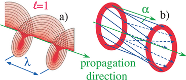
Thus the rotational Doppler effect may be readily deduced from the linear Doppler effect. Both effects share a common origin.[16]
2.2 Interpretation in Terms of Rotation of the Detection
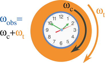
The rotational Doppler effect can also be interpreted in terms of rotation of the detection system. It doesn't need to evoke the linear Doppler effect. It is only a matter of rotation of the frame associated with the emitter regarded to the frame associated with the receiver.

Then the light angular frequency is shifted by a quantity , which again corresponds to the formula of the rotational Doppler shift of Equation 1.
Actually, this picture has been nicely proposed by M. Padgett in ref. [26]: “Place a watch at the centre of a rotating turntable, and, viewed from above, its hands will seem to rotate more quickly. This classical effect applies to all rotating vectors, for example to the spatial pattern of the electric field of any light beam carrying angular momentum. The electric-field vector rotates at the frequency of the light, but an additional rotation of the beam about its axis of propagation will speed up or slow down the field rotation, resulting in a frequency shift proportional to the rate of rotation of the beam.” This idea is depicted in Figure 3. This picture is also analogous to the one-day gained by Phileas Fogg on his eastward around-the-world circumnavigation in J. Verne's famous novel “Around the World in Eighty Days”.[27] It is only a matter of rotation between the frames.
2.3 Interpretation in Terms of Energy Conservation
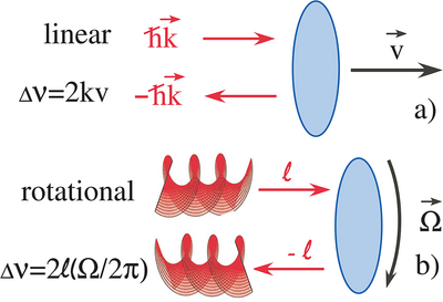
Of course, this interpretation of the Doppler effect in general is not limited to optics and can be generalized to the whole electromagnetic spectrum, electron and neutron beams, and in acoustics as well.
In this section, we have presented three different interpretations of the rotational Doppler. They all lead to the same Doppler shift formula of the electromagnetic field. However, depending on the experimental situation, some interpretations may be more suitable than others (see in particular Section 4.2).
3 Experimental Observations of the Rotational Doppler Effect
3.1 How to Detect the Rotational Doppler Effect?
The technics that are used for measuring the linear Doppler effect can be applied to the detection of the rotational Doppler effect. It is only a matter of detecting a change of frequency. However, there is a striking difference between the linear and rotational Doppler effect. Actually, the linear Doppler effect equals , whereas the rotational Doppler effect equals . Let us consider a typical velocity of m.s−1 and an electromagnetic wave in the radio frequency domain (frequency of 3 GHz), m−1, the Doppler shift equals Hz. Let us now consider a beam in the visible part of the spectrum, at wavelength μm, in the green. The wavenumber is m−1 and the Doppler shift is Hz, that is, in the tens of MHz range which is rather high. Sometimes, one uses two close wavelengths to bring back the Doppler signal on the beat frequency in a smaller frequency range.
On the contrary, as can be seen in Equation 1, the rotational Doppler effect is independent of the frequency of the incident wave. For a typical rotation frequency of Hz, and a topological charge of , the Doppler shift is Hz, whatever the wavelength. In the visible, this is very different from the linear Doppler effect. It is not the same frequency range. For low rotation speed, the shift could even be below the Hz range. This could be a problem when using a spectrum analyzer. It must have a very good resolution (i.e., in the Hertz range or even below).
When using radio waves, the frequency of the rotational Doppler shifted beam could be directly measured using a spectrum analyzer or a vector network analyzer,[36] with frequency shifts in the Hz range. The same technics cannot be used in the optical domain. Optical spectrum analyzers don't have such a resolution. The resolution of such analyzer is around 0.1 nm, which corresponds to 30 GHz for a wavelength of 1 μm. Even Fabry-Perot interferometers don't have the frequency resolution, which is usually about 10 MHz. The easiest way to perform a frequency shift measurement is to investigate for a beat frequency against a unshifted signal, thus performing a self homodyne measurement. The beat frequency directly measures the frequency shift.
An elegant alternative to this could be to use a superposition of beams with opposite topological charges. The beam carrying angular momentum experiences a shift, whereas the beam carrying angular momentum experiences a shift. The beat angular frequency between the two shifted beams then equals .[37, 38] It is worth noting that the interference pattern leads to a daisy like picture that rotates depending on the beat frequency.[39] Since the two OAM beams experience the same linear Doppler shift, this method is insensitive to the linear Doppler effect. One may however questioned the angular momentum conservation in this particular case. Since one beam transfers to the rotating object whereas the other beam transfers , there is no resulting OAM transfer to the rotating object.
Nevertheless, such measurements cannot determine whether the frequency shift is positive or negative. Yet, the sign of the shift can be determined with self heterodyne measurements. The reference beam is frequency shifted (for example using acousto-optic modulators) by a fixed known quantity . The rotational Doppler shift is deduced from the beat frequency , . This quantity () can be positive or negative depending on the sign of the rotational Doppler shift.
3.2 Emitter and Receiver Rotating Regarded to Each Other
Let us consider the simplest situation where the emitter and the receiver are rotating regarded to each other. In Figure 5a, the emitter is rotating regarded to the fixed receiver. The receiver is composed of a lens that focuses the light into a fiber. Then, a coupler mixes the detected signal with a reference beam. As one considers the phase of the incoming beam in the observer frame, the phase rotates at an angular frequency Ω, as can be seen in Figure 5c. This leads to a frequency shift that equals . In this experimental configuration, rotational Doppler shifts have been clearly evidenced. It has mainly been reported in acoustics,[40, 41] although the same phenomenon could be observed in radio or optics. Curiously, in acoustics, in Reference [41], the authors report a negative rotational Doppler shift that is higher than the carrier sound frequency. This leads to an observed negative frequency. Then the orbital angular momentum reverses its sign in a spectacular way.
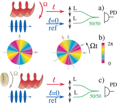
Actually, this situation is very similar to the one depicted in Figure 5b, where an element on the optical path that changes the topological charge of the beam, such as a phase plate in this case, is rotating at angular frequency Ω. The phase of the beam is also rotating, generating a frequency shift that equals , being the change of topological charge induced by the element. This kind of experimental set-up has been used several times to evidence a rotational Doppler shift both in radio,[36, 42] or in optics.[43, 44] Note that in this later case that uses a phase plate, it is not possible to use the homodyne technics with beams of opposite topological charges, since both beams experience the same topological charge variation. One needs to beat the signal against an external reference beam. However, it is still a valuable technics when the element on the optical pass reverses the topological charge of both beams. This is what happens with a dove prism[45] for example.
3.3 Reflection on a Surface that Changes ℓ
The linear Doppler effect has been widely used to measure the velocity of reflecting surfaces. However, as explain previously, the rotational Doppler effect is associated with angular momentum transfer. Thus, the topological charge (or the polarization) of the incoming beam must change during interaction to experience a rotational Doppler effect. There cannot be any rotational Doppler effect upon perfect simple reflection. This then strongly limits the use of the rotational Doppler effect on reflection to very special reflectors. In particular, it can be observed on phase conjugated mirrors,[46, 47] and has been evidenced on metasurfaces,[48, 49] q-plates[50] and helicoidal reflectors[49, 51] or prisms.[52] All these systems change the topological charge of the beam upon reflection. We will concentrate in the following on the reflection on a prism, without any lost of generality.
Let us consider the experimental set-up of Figure 6a. A spatial light modulator transforms the fundamental beam of a low power He-Ne laser (wavelength nm) into a superposition of and Laguerre Gaussian (LG) beams. This superposition impinges on a right angle prism. It undergoes two 45° total internal reflections. Then the beam is transformed into a beam, whereas the is transformed in a beam. The prism exchanges the topological charges. The beat frequency is registered on a photodiode and the reflected image is view on a screen. It corresponds to a daisy flower with only two petals.
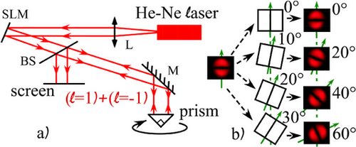
As can be seen experimentally on the Figure 6b, as the prism is rotated by an angle θ, the interference pattern rotates by an angle . As the prism is now rotated uniformly at an angular frequency Ω, the daisy flower rotates at an angular frequency 2Ω, which also corresponds to the beat frequency between the two LG beams. The experiment can be reproduced using higher values of ℓ. The beat frequency would then be . Analogously, for spin angular momentum, a superposition of right and left polarized beams (which indeed corresponds to a linear polarization) impinging on a rotating right angle prism would be transformed into a linear rotating polarization at twice the rotating angular frequency of the prism. The beat frequency is then equal to 2Ω as well. It is worth noting that in the case of a reflection on a conical prism, there couldn't be any Doppler effect since the angular momentum doesn't change upon reflection.[53]
3.4 Diffusion on a Rotating Surface
The rotational Doppler effect has been widely used to measure the rotation of a surface that is diffusing light, mostly in the case of a uniformly rotating surface, such as a diffusing rough disk (see Figure 7).[37, 44, 54] Sometimes, one also uses a rotating pattern on a SLM to emulate the spinning object.[38, 55] In this kind of experiment, a vortex beam with a given topological charge ℓ impinges on this rough diffusing surface. For small scatterers, the diffused light doesn't carry OAM anymore. There is thus a ℓ topological charge variation leading to a rotational Doppler shift . This shift can be detected either from a beat frequency with a reference signal or using a superposition of beams with opposed topological charges as depicted in Section 3.1.
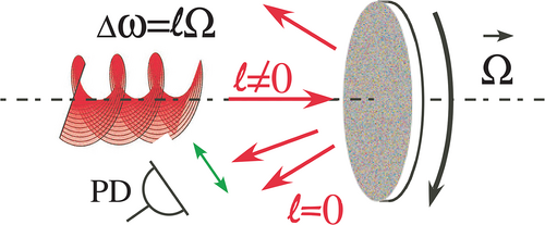
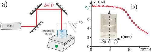
A very similar experimental configuration has also been used in the case of light scattering in a liquid[56-59] (see Figure 8a). An OAM carrying optical beam is scattered by a rotating fluid. There is however a striking difference. Whereas the rotation is uniform for the diffusion by a rough surface, the rotation is non uniform in the case of a liquid. There is a decrease of the rotating frequency with the distance from the rotation axis. One can then benefit from the ring intensity structure of LG (Laguerre Gaussian) beams to probe the fluid at a given distance from the axis. One can then reconstruct the fluid rotation distribution either by changing either the focus of the LG beam or the topological charge of the beam. It has been successfully used to reconstruct a ranking liquid vortex in particular[59] (see Figure 8b).
3.5 Rotational Doppler Effect using a Fundamental Gaussian Beam
Up to now, we have exclusively considered an incoming beam that carries OAM. One can however wonder whether a rotational Doppler effect could be evidenced using a fundamental Gaussian beam, in a situation similar to the one encountered for the usual linear Doppler effect. Let us consider the situation depicted in Figure 9. The fundamental beam of a laser (it could also be a usual plane wave), impinges on an object having a p-symmetry. It particular, it means that the object is invariant by a rotation. It could mimic an ideal propeller with p blades for example. Without taking into account diffraction, the transmitted light corresponds to Figure 9. It is not a fundamental beam any more. It could be decomposed into a LG basis. In particular, modes with the same p symmetry, corresponding to topological charges multiple of p (, n being an integer) would appear in the decomposition of the transmitted beam.
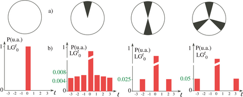
As the object is set into rotation at an angular velocity Ω, the phase of the different LG beams will rotate as well. As previously described, this leads to a rotational Doppler shift that equals . Such experiment has been performed using a modal decomposition of the transmitted light thanks to a Multi-Plane Light Convertor (MPLC).[60, 61] Briefly, on a theoretical point of view, any unitary spatial transform can be implemented by a succession of transverse phase profiles separated by free space propagation for optical Fourier transforms. The MPLC cavity is formed by one mirror and one reflective phase plate, performing the successive phase profiles and optical transforms, to realize a given unitary spatial transform, with low optical losses and high modal selectivity. This could be perform for any wavelength.
Rotational doppler shifts have been reported on the transmitted light[62, 63] on the LG modes that are multiple of the symmetry of the object, with excellent agreement with the above predictions. A rotational Doppler effect has also been reported from a fundamental beam diffracted by a rough surface that have been embossed with a given rotational symmetry.[37] This can also be observed using non-zero incoming LG beam.[64-66] It is only a matter of decomposition in the LG basis behind the occulting object. Besides, instead of being used in a bistatic configuration that investigates the transmitted light, the same principle can be used in a monostatic configuration in reflection,[67] leading to the same kind of conclusion: rotational Doppler effects have been evidenced. Experiments have also been performed on light that changed its spin due to birefringence from a rotating gas, but using the rotational Doppler effect with circularly polarized light (SAM).[68, 69]
3.6 Rotational Doppler Effect in Non-Linear Optics

4 Discussion and Perspectives
4.1 Rotational Doppler Effect Upon Reflection on a Rotating Surface
By analogy with the usual linear Doppler effect, the most intuitive experimental set-up one can think about, is the simple reflection on a rotating mirror. However, as we have already mentioned, since there is no angular momentum exchange upon reflection on a simple mirror, it couldn't be any rotational Doppler effect. Yet, there have been several reports on rotational Doppler effect observation upon reflection on a simple rotating surface, mainly in the radio domain.[75-78] Besides, Doppler signal is usually weak compared with the total reflected signal. Anyway, we couldn't question their experimental observations. However, one may raise some doubts about their interpretation.
The most likely explanation is the following. It could be there is some scattering from the surface, since it is usually not a perfect reflecting surface, or some diffraction by the edges of the surface. Then, what the author would have observed is the scattering of OAM by a rough surface, as described in Section 3.4. This would then lead to a rotational Doppler effect. Since the scattering is weak, the rotational Doppler effect is also weak. Whereas their observations are surely correct, care may be taken regarding to their interpretation.
4.2 Beam Axis and Rotation Axis that don't Coincide
In most of the experiments involving the linear Doppler effect, one considers a plane wave interacting with a moving object. Upon oblique incidence on the moving target, one has to include the angle of incidence β into the well-known Doppler formula. The formula for the change of frequency , ω being the light angular frequency, v the relative velocity. As one considers a Gaussian beam, it may be some transverse effects,[79] that could be also encountered using structured light such as LG beams.[80, 81] Up to now, in this review, we have always implicitly assumed that the probing beam axis and the rotation object axis coincide. What happens if they do not coincide?
Some authors have already considered a misalignment between the two axis,[82-84] whereas others consider an OAM beam impinging on a spinning object at oblique incidence.[85, 86] Actually, as the authors have shown, it is only a matter of modal decomposition of the incident beam into a LG beam basis attached to the rotating object.[38, 87-89] Let us for example consider the case of a misalignment, where the center of the incoming beam is shifted by a distance d regarded to the rotation axis. The decomposition into a LG basis can be performed rather easily and evaluated numerically. The results appear in Figure 11. Figure 11a,b corresponds to a fundamental beam and the LG beam for a topological charge equal to 1, with , respectively. Figure 11c,d corresponds to the same beams but with , w0 being the beam waist.[23] It can be clearly seen that several modes, that do not correspond to the incoming beam, appear in the decomposition. Besides, as the distance d increases, more for and more components are present within the decomposition.
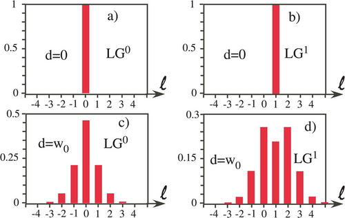
As the surface rotates and since the topological charge must change upon interaction, like in the case of scattering by a rough surface, several rotational Doppler harmonics appear, corresponding to each topological charge in the decomposition. This has been indeed experimentally evidenced in ref. [82]. Interestingly, in this article, they also show that the picture of the rotational Doppler shift based on the linear Doppler shift developed in Section 2.1 leads to a broadening of the beat frequency. This is in contradiction with the experimental observations. They conclude that the correct interpretation is that the incoming beam has to be decomposed in the LG basis associated with the rotating systems, as described above. This then leads to several peaks. This interpretation corresponds to the experimental observations. It demonstrates the limits of the interpretation of the rotational Doppler effect in terms of linear Doppler effect. The same decomposition technics could be used in the case of an oblique incidence of the incoming beam, as discussed in ref. [87]. The number of modes and their strength increase with the increase of the angle of incidence. There also could be a mixing of the misalignment and of oblique incidence. It is only a matter of decomposition in the LG basis associated with the rotating object.
It is worth noting that in the case of a perfectly reflecting surface with a misalignment of the incoming beam axis and the rotation axis, such as in Figure 11c,d, several LG modes appear in the decomposition. One could then suspect the existence of a rotational Doppler effect. However, for each of the modes in the decomposition, the reflection of the mode on the surface is not accompanied by a change of the topological charge. It is only a simple reflection. There is thus no rotational Doppler shift. Nevertheless, in the case of scattering by the surface, as it is followed by a change of the topological charge of each beam within the decomposition, it leads to several Doppler shifts, even for a fundamental incoming beam. In particular, it means that the scattering of a fundamental beam by a rough surface with some misalignment could lead to a rotational Doppler effect. Whatever the charge of the incoming beam, the contribution of the mode not corresponding to the incoming beam, increases with the misalignment and with the oblique incidence. The appearance of several harmonics in the scattered spectrum can even be a non-alignment criterion.[88, 90]
The rotational Doppler effect, even for a misalignment or an oblique incidence, is well characterized in the case of a uniform rotation, such as the diffusion by a rough surface. There is only one unique rotational velocity and the experimental data can be easily interpreted. It is close to being a routinely used technics. However, there is no experimental nor theoretical study in the case of a non-uniform rotation such as the one encountered in fluid vortices. In particular, the rotational velocity decreases with the distance from the axis, and it is difficult to perform any off axis investigation of such vortices. Experimental studies remain to be performed in these cases, which can be of particular importance for applications such as in tornados[91, 92] or ocean vortices survey,[93, 94] for example. One would then be able to perform a complete mapping of these fluid vortices independently of the beam and fluid vortex alignment. This would be particularly interesting in the monitoring of these effects.
4.3 Scattering by Small Particles, from Colloidal Suspension up to the Atomic Scale
In the preceding sections, we have mainly dealt with rotational Doppler effects on macroscopic objects and specially on rotating flat surfaces. Could it be also evidenced on micrometer size particles up the the atomistic or molecular level? This would be of particular interest in the rotation control of spherical micro particles and cells.[95, 96] Actually such experiments have been already performed on micro-elements that are rotating within a trap,[97, 98] or on the axis of a rotating fluid[57] using an OAM beam as a probe beam. The rotational Doppler effect would enable to probe the rotational diffusion of spherical colloidal particles.
In the case of nanoparticles, based on a quantum mechanical model, it has been recently predicted a circular dichroism in optically isotropic particles depending on their geometry.[99] Besides, particles with one dimensionally confined electron motion, perpendicular to the rotation axis, such as nanorings or nanocrosses exhibit a splitting of their optical resonance that is twice the rotation frequency. It has also been predicted a rotational Doppler cooling, analogous to the linear Doppler cooling for those nanosystems.[100]
Experiments have also been conducted on elastic scattering on atoms and molecules. Actually, a broadening of spectral lines have been observed that have been attributed to the rotational Doppler effect.[101] The authors compared the line-widths of resonance lines with opposed topological charges versus the same topological charges. For a rotating system, in the case of a single topological charge, the light beam experiences the same Doppler shift, whereas for opposite topological charges, the two beams experience opposite rotational Doppler shift. The line-width are shown to be broadened in the case of opposite topological charges. The same observation has also been reported on molecules with opposite polarized beams.[102] These promising first measurements also show that the rotational Doppler effect could be a valuable tool even at the microscopic scale.
5 Conclusion
Since the preliminary work in the eighties'[13, 14] on polarization, and after its observation with Orbital Angular Momentum (OAM) carrying beams at the end of the nineties',[42, 45] the rotational Doppler effect has experienced an exponential reagin of interest. It has been evidenced that the topological charge has to change during interaction between the OAM carrying beam and the rotating element that characterize the rotation. It is deeply linked to angular momentum transfer. Many experimental works have reported its observation, either with elements that change the topological charge or via scattering. Although some efforts remain to be done for example in the scattering from a rotating fluid or at the microscopic scale, the rotational Doppler effect has now reach a certain kind of maturity. We anticipate that it will become as indispensable a tool in a very large number of fields as the linear Doppler effect.
Besides, the linear Doppler effect is associated with a transfer of linear momentum which is generally speaking a conserve quantity and is linked to the energy via the Poynting theorem.[103] The rotational Doppler effect is associated with the transfer of angular momentum, which is also a conserved quantity independent and not derivable from energy nor linear momentum.[104, 105] However, in the electromagnetic theory, there is another quantity that is conserved. It is called the boost momentum density.[105-107] It is related to the generators of the so-called Lorentz boost in special relativity.[108] It couples a Cartesian direction with time. In a more formal description, it equals the difference between the moment of energy density and the product of linear momentum density by the elapsed time. For electromagnetic fields in free space, the three components of the boost momentum of energy (one for each of the three orthogonal Cartesian directions) are constant of motion. One may then wonder whether it might be a Doppler effect associated with this quantity.
Acknowledgements
The authors acknowledge fruitful early discussions with C. Brousseau.
Conflict of Interest
The authors declare no conflict of interest.
Biographies

Olivier Emile received his Ph.D. from the University of Paris 6 (France) in 1993, in laser cooling of atoms. He has been appointed as an assistant professor at the University of Rennes in 1994 and as a full time professor at the same university in 2002. His main research activity includes lasers dynamics, evanescent waves, atomic physics, optofluidics and angular, and orbital momentum of light.

Janine Emile received her Ph.D. from the University of Rennes (France) in 1993 in condensed matter. She has been appointed as an assistant professor and as a full time professor in 1993 and 2007, respectively, still at the University of Rennes. Her research interest focuses mainly in soft matter (colloidal suspensions, optofluidics and liquid films). She has also been interested in studies on the orbital angular momentum of light and its application to particle manipulation. She is Dean of the physical and chemistry department.


