Mechanical Characterization of hiPSC-Derived Cardiac Tissues for Quality Control
Abstract
Heart disease is one of the leading death causes in developed countries. To facilitate heart rehabilitation, engineered cardiac implantation has emerged as a promising alternative to organ transplantation. Currently there is no quantitative standard to ensure the safety and functionality of the engineered cardiac tissues intended for clinical uses. In anticipation of the clinical application of the engineered cardiac tissues to heart disease patients, a suite of methods is assembled to evaluate the mechanical characteristics critical to cardiac functions, including contractility, viscoelasticity, and dynamic stress distribution. As a proof of concept, 3D bioprinted cardiac tissues derived from human induced pluripotent stem cells are tested. First, the engineered cardiac tissues labeled with particles are recorded and tracked to determine spatially and temporally variable contraction forces. Viscoelastic properties are measured using magnetic tweezers. The results are used to compute 3D force and stress distribution over the engineered tissue by finite element method. In summary, a framework is developed to assess clinical-grade engineered cardiac tissues and determine the appropriate value ranges suitable for implantation. The results relating contractility, intrinsic mechanical properties, and stress distribution in the engineered tissue, can also inform better design for future fabrication of engineered tissues.
1 Introduction
Cardiovascular diseases are the leading cause of death worldwide.1, 2 In particular, coronary artery disease is a major contributor to mortality, with ≈935 000 people per year in the United States experiencing acute myocardial infarction (MI).3 The underlying pathology of MI is associated with blockage of a coronary artery, leading to reduced blood flow to the heart and ultimately necrosis of heart tissues and cells. During MI, seminal structural and functional changes in the heart occur. These ischemic changes can result in life-threatening complications, such as wall thinning and rupture, disrupted vasculature, fibrosis, and development of heart failure.4 Given the limited proliferative capacity of mature cardiomyocytes, effective healing from self-regeneration is rare, if not impossible. The only definitive treatment currently available for heart failure resulting from MI is organ transplantation. However, the prohibitive costs of organ transplantation, immune response by the organ transplant, and the limited supply of suitable organ donors remain difficult to overcome. Therefore, other innovative and effective treatments are highly desirable.
Engineered tissue grafts have been extensively explored as an alternative therapy to replace damaged or diseased tissues.5 In particular, engineered cardiac tissues of various sizes and shapes are emerging as promising therapies to treat acute MI, augment contractile function, and promote vascularization. Various engineered cardiac tissues have been developed using acellular biomaterials,6 cell–biomaterial hybrids,7 or scaffold-free tissues.8 Although engineered cardiac tissues have been implanted in animal models, clinical application remains tremendously challenging, because there is no standardized method to evaluate the primary function of cardiac tissues before implantation. In anticipation of the future clinical application, at least three aspects of the engineered cardiac tissues are required to be evaluated to ensure the feasibility and safety. First, cardiac patches should be fabricated with the appropriate dimensions, shape and cell contents for optimal repairing efficacy.9 Second, given that contractile force and beating frequency have been shown to be a good indicator whether postimplantation integration between the engineered tissue and the patient's heart is likely,8, 10 the contractile forces and frequencies should be evaluated to ensure proper cardiac function upon integration with the damaged heart.11-14 Third, given that the intrinsic mechanical properties of the engineered cardiac tissues can be used to predict whether the tissues can sustain the stress during heart contraction6 during the implant-heart integration process, the parameters such as elastic modulus, viscosity, shear modulus, bulk modulus, and dynamic stress distribution should be assessed to verify structural integrity.15
Though force measurement techniques such as tissue contraction force microscopy11 or tissue gauge16 have been developed previously, mapping of mechanical forces and/or stress in contractile tissues in 3D and in arbitrary shapes is yet to be established. Given that cardiac tissues are heterogeneous in nature,17, 18 the lack of precise force mapping imposes uncertainty when predicting whether a specific engineered cardiac tissue is suitable for clinical use. Such uncertainty is particularly impactful given that stress and force are correlated with the pathology of the tissues or organs.19 For example, tissue gauge does not provide spatial information in local stress experienced by the tissue, and a structurally vulnerable spot in the engineered tissue might be overlooked. In addition, unlike the cardiac tissues in vivo or cardiac organoids formed by mixing cells with substantial extracellular matrix (ECM) proteins, it might be clinically beneficial not to add external ECM in order to minimize the immunogenicity after implantation.20-24 For example, it was reported that patients treated with Zyderm, one of the most commonly used collagen implanting materials, developed susceptibility to abscess formation and local necrosis,25 because of undesired immune responses. In addition, it is possible that some patients are predisposed of collagen allergy or zoonotic disease transmission.26 However, the exclusion of the external ECM results in much softer and more fragile tissues before maturation, since the structural support is negligible to reinforce the tissue integrity by the ECM during the fabrication. The tensile strengths of the engineered cardiac tissues were low relative to the real cardiac tissues in the heart. We have observed that occasionally the engineered tissues would disintegrate spontaneously during the contraction; occasionally external strain more than 30% would also disintegrate the engineered tissues into smaller pieces (data not shown). It is designed that the mechanical property of the engineered cardiac tissues will continue to evolve and become comparable to healthy in vivo cardiac tissues after the implantation. As a result, few, if any, existing mechanical measurement techniques established for cardiac tissues can be used to examine these hypo-immunogenic engineered tissues at the desired resolution prior to implantation. Methods such as tissue gauges16 and micro-indentation27 cannot be used in this context. It also should be noted that although previously developed optical flow–based methods can be used to track the contractile motion the cardiac tissues, they cannot measure the local contractile forces over the tissues.
To overcome this challenge, we developed a force/stress measurement technique as the basis to assess the properties critical to cardiac function as described above. Engineered cardiac tissues in the form of spheroids or patches were labeled with particles conjugated with appropriate antibodies and subjected to a series of measurements. The particle displacement during contraction of the cardiac tissues was quantified using single particle tracking (SPT) or particle image velocimetry (PIV). Based on the particle displacement, contractility parameters were estimated. We validated our techniques by testing tissues treated with Y-27632, a drug known to reduce contractile forces, as a benchmark. Viscoelastic properties, namely the elastic modulus and viscous friction, were also measured using magnetic tweezers. The measurement results were used to compute the force and stress distribution over the engineered tissue by finite element method (FEM). To run the simulation, we utilized two mechanical models, an elastic model and a viscoelastic model, and subsequently compared deformation and stress. We found that elasticity predominantly governs the mechanical behaviors of the tissue more than viscosity. Overall, we demonstrate that the quality of engineered cardiac tissues can be assessed by a series of mechanical measurements, and the data generated will inform a better design for future fabrication of engineered tissues.
2 Results
2.1 Fabrication of Personalized Engineered Cardiac Tissues Derived from Human Induced Pluripotent Stem Cells (hiPSCs)
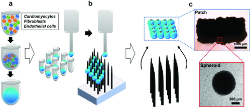
To fabricate cardiac tissues applicable to treat patients with various heart diseases including myocardial infarction,28 congestive heart failure,29 and cardiomyopathy,30 hiPSC-derived cardiomyocytes, human cardiac fibroblasts, and human umbilical vein endothelial cells were combined to form spheroids with the average diameter of 500–600 µm as the basic unit of the engineered cardiac tissue (Figure 1a). It should be noted that unlike other fabrication methods, our cardiac spheroids were formed without the addition of ECM, such as Matrigel or collagen I, which is derived from sources other than the donors of the hiPSCs. This is to improve cell–cell contact, thereby maintaining cellular function. For cases where a larger area of engineered tissue is needed, the cardiac spheroids are combined into patches of the desired dimension.8, 31 In this study, we tested the functionality and mechanical properties of the cardiac tissues consisting one or more spheroids. The patches containing multiple spheroids (n = 16) were constructed using a needle array–based 3D bioprinter, which is equipped with custom-built software so that individual spheroids can be patterned via vacuum suction and precision placement. Spheroids were placed into the predesignated needle positions (Figure 1b), and form a patch-like structure upon coalescence after appropriate an incubation period. After decannulation from the needle array, the newly formed patches were cultured for additional time to allow the gaps in the patch to be filled with cells and cell-secreted molecules (Figure 1c).
2.2 Extraction of Contractile Profiles of the Engineered Cardiac Tissues by Particle Tracking
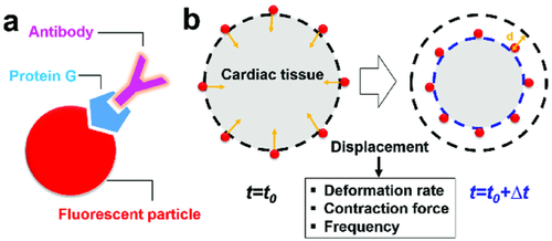
To test the contractility with detailed spatial information within the engineered cardiac tissues, we implemented a particle-based approach. The engineered cardiac tissues were graded by visual inspection performed by a cardiac surgeon based on the imperial and qualitative standards obtained from the previous studies.8, 31 The tissues deemed suitable for implantation were used for the measurement. 40 µm sized particles were coated with antifibronectin antibody which targets the ECM of the tissue, and subsequently used to label the engineered cardiac tissues (Figure 2a). Particle displacement (Movie S1, Supporting Information) was measured by a SPT algorithm. Based on the particle displacement, three parameters representing the mechanical behavior of cardiac tissues were obtained: deformation rate or velocity, frequency, and contraction force. The deformation rate was obtained by dividing the displacement of particles by the time interval (∆t = 50 ms). The frequency was evaluated by direct calculation of the peak-to-peak duration or by thresholding in Fourier domain, where the dominant frequencies corresponding to the magnitudes above 80% of maximum amplitudes were identified and averaged (Figure S1, Supporting Information). The values obtained from both methods agreed with each other. The beating rate of both cardiac spheroids and patches is 0.61 ± 0.13 Hz, agreeing with the physiological heart rate.32 Our measurements showed that cardiac spheroids and patches exhibit comparable beating frequency.
We primarily used SPT to track particle movement. But to demonstrate that our platform of tissue characterization is modular and robust, we also tested the result using another algorithm, PIV for verification. PIV compared two successive images by cross-correlation to determine the displacement and velocity of the field. We compared the results obtained by SPT and PIV (Figure 3a,b). The mean peak displacement of SPT and PIV is 4.3 ± 0.3 and 4.6 ± 0.3 µm, respectively. The mean peak velocity of SPT and PIV is 86.0 ± 5.6 and 91.1 ± 6.8 µm s−1, respectively. No significant differences were observed in the velocity magnitudes and beating profiles over time estimated by SPT and PIV by Student's t-test (Figure 3b).

The particle drag forces were then calculated using Equation 1. The average maximal contraction force of single spheroids was calculated as 330 ± 5.3 pN, resulting in the maximal compression pressure of 0.203 ± 0.003 Pa. We also tested the maximal contraction force of the cardiac patches, where four spheroids coalesced, which was calculated as 452 ± 215 pN, resulting in the maximal compression of 0.595 ± 0.283 Pa. Our measurement showed that cardiac spheroids and patches exhibit comparable contractility.
2.3 Mapping Dynamic Contractile Forces in the Engineered Tissue
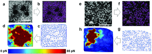
Next, we set to create force maps in the cardiac tissues (Figure 4). Local velocity was extracted by SPT, followed by mesh generation through the Delaunay algorithm where particle locations serve as coordinates of the nodes (Figure 4a–c for spheroid and Figure 4e–g for patch). Drag forces were calculated based on Equation 1 by inputting the particle velocity and implementing linear interpolation throughout the mesh (Figure 4d,h).
To validate our methods, we treated the engineered cardiac tissues with Y-27632 prior to the measurement. Y-27632 is a Rho-associated protein kinase (ROCK) inhibitor with known effects on cardiac contractility.36 ROCK inhibition results in decreased myosin light chain phosphorylation, required for contraction force generation. By comparing the mean contraction forces, mean peak forces (Figure 5a,b) and force maps (Figure 6) between the Y-27632-treated cardiac tissues and the control, it was confirmed that our platform could detect the reduction in contractility. In particular, we found Y-27632-treated cardiac tissues exhibited an ≈2.2-fold decrease in mean peak contraction forces compared to the control (Figure 5b). However, no significant difference in frequency between the control (0.61 ± 0.13 Hz) and the Y-27632-treated tissues (0.71 ± 0.14 Hz) was observed (Figure 5c), consistent with the previous studies where ROCK inhibitor has been reported to affect force generation but not beating rate when a modest dosage is applied.37

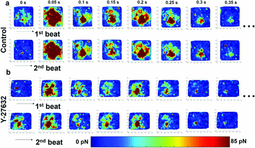
It should be noted that the force maps and velocity field maps of the cardiac tissues revealed that the contraction occurred in a propagating manner with varied local forces (Figure 6 and Figure S2, Supporting Information). In other words, nonuniform forces with unsynchronized local contractions were observed in the engineered cardiac tissue, resembling the spatially variable contraction forces in terms of phase and magnitude exhibited by the heart.
Closer inspection of the dynamic force maps of Y-27632-treated and control cardiac tissues (Figure 6) revealed that despite the differences in local force magnitude, the beating patterns were similar. It is consistent in both groups that the highest forces were constantly observed in the center of the tissues, while the periphery showed maximal contraction at 1.38 ± 0.36 and 1.12 ± 0.17 s in control and Y-27632-treated tissues, respectively, after reaching the relaxation state of the previous beating cycle. The periphery of the tissue then gradually relaxed to the resting state until the next cycle. Furthermore, we observed that the beating pattern of the same tissue remained consistent between different cycles in both groups, indicating unimpaired self-pacing in the engineered cardiac tissues.
2.4 Characterization of the Tissue Viscoelasticity Using Magnetic Tweezers
Next, we set to standardize the process to evaluate the viscoelastic properties of the engineered cardiac tissues to ensure the integrity of the engineered cardiac tissues. It should be noted that viscoelasticity might not be the dominant effect in the mature cardiac tissue in vivo. However, unlike the functional and fully mature heart tissues, viscoelasticity might dictate the strain–stress response in premature engineered cardiac tissues containing only trace amount of ECM,38-42 which contributes to the elasticity of the tissue significantly. The elastic modulus and viscous friction of the cardiac patches thereby were surveyed using magnetic tweezers (Figure 7a) and extracted based on the Kelvin–Voigt four-element model (Figure 7b,c). The four-element Kelvin–Voigt model was previously shown to be appropriate to characterize the mechanical properties of the tissues or cells.43, 44 The external magnetic field was applied using a pencil-shaped 416 steel probe magnetized by a Neodymium magnet with a surface field of 0.4 Tesla. The field gradient produced by the magnetic tweezers drove the movement of the antifibronectin-coated paramagnetic particles bound to the cardiac tissues. The tissue-bound particles were tracked by SPT, and the displacement of the particles was calculated and plotted over time (Figure 7d).
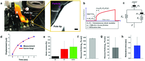
The experimental data and the fitted curve showed good agreement (R2 > 0.9) (Figure 7d). The elastic modulus and the viscous friction were computed, yielding the result E0 and E1 of 144 ± 24 and 612 ± 510 Pa, respectively; µ0 and µ1 of 1151 ± 33 and 71 ± 69 Pa s−1, respectively (Figure 7e–g). The relaxation time (τ) was determined to be 0.49 ± 0.33 s (Figure 7h). These measurement results were then used as the input values to construct the computational model for 3D force maps described in the following section.
2.5 Building a 3D Stress Map of the Engineered Cardiac Tissues Implementing FEM
Some engineered cardiac tissues were observed to break into small pieces during contraction, indicating the mechanical properties of those tissues were not sufficient to withstand the stress imposed by the spontaneous contraction. Therefore, evaluating the stress distribution in 3D over the engineered tissue during the contraction provides the information regarding the minimum stress tolerance of the tissue. FEM was implemented to construct the 3D stress map computationally. The measurement results obtained in the experiments, including the deformation, the contractile velocity, the elastic modulus, the viscous friction and the beating frequency were incorporated in the model (Figure 8). Additionally, the dynamic shape and size changes during the deformation are also required for the simulation. The spheroids used in this work were ≈600 µm in diameter (Figure 8). The contraction of the spheroids universally exhibited unsynchronized deformation based on time-lapse images (Figure 8a,b), which can be described as follows: a relatively large deformation was first observed (Figure 8a), followed by a second, smaller deformation at the opposite side of the spheroid (Figure 8b). Taking advantage of similarities among the cardiac spheroids, in terms of size and deformation dynamics, we assigned a simple contraction pattern for simulation (Figure 8c). Based on the designated pattern, the virtual cardiac spheroid was constructed and segmented into eight different parts (Figure 8d). Two measured displacement values, 15 and 6 µm, were used as inputs at the bottom left and top surfaces with 0.1 s of time delay as the boundary conditions.
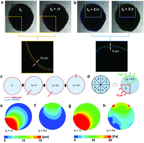
The simulation demonstrated that the maximal deformations of the viscoelastic model for both the first and second contractions were located at the surface, which was designated as the boundary condition because of the sudden force changes (Figure 8e,f and Figure S3a, Supporting Information). Maximum principal stresses were found to be 609.48 Pa at t0 and 64.42 Pa at t0 + 2Δt, respectively (Figure 8g,h). Overall the deformation and stress distribution of elastic and viscoelastic models are comparable (Figure S3a, Supporting Information). Similar to the viscoelastic model, the maximal deformations and stress of the elastic model were found at the outer surface of the spheroid. The magnitude of maximal deformation (16.46 µm) for the viscoelastic model is comparable to, though slightly larger than, that obtained from the elastic model (16.03 µm). The surface average stress magnitudes in the elastic model, ranging from 17.36 Pa at t0 + 2Δt to 44.95 Pa at t0, are also similar to values of the viscoelastic model, ranging from 16.22 Pa at t0 + 2Δt to 42.60 Pa at t0. The stress maps generated by the computational model exhibit the spatially variable pattern in magnitudes comparable to our experimental observations in the engineered cardiac tissues.
3 Discussion and Conclusion
In this study, we developed a suite of methods to evaluate the mechanical properties of engineered cardiac tissues. The contractility and the mechanical properties of the tissue were measured by particle tracking and magnetic tweezers, and the 3D stress map of the tissues was generated by simulation with measured values as inputs. We observed that the viable engineered cardiac tissues fit for successful implantation had the following properties: the beating pattern of the same tissue remained consistent between different cycles; the maximal contraction force was 452 ± 215 pN with maximal compression of 0.595 ± 0.283 Pa; elastic moduli were 144 ± 24 Pa (E0) and 612 ± 510 Pa (E1), and the viscous frictions were 1151 ± 33 Pa s−1 (µ0) and 71 ± 69 Pa s−1 (µ1), respectively, with the relaxation time (τ) 0.49 ± 0.33 s. Multiple methods have been developed to measure the contractility of the cardiomyocytes or cardiac organoids,47-49 such as tissue contraction force microscopy11 and tissue gauges.16, 50 However, most of these methods are intended for characterizing the contractility under different treatments, in order to gain more in-depth knowledge of cardiac biology. For example, the deformation during contraction of the cardiac monolayers or 2D thin tissues, cultured on elastic substrates, were measured; and the stress experienced by the tissues was calculated, assuming the thin tissues or monolayers were hyperelastic.51-54 As for 3D engineered tissues, tissue gauges were developed to measure the contractility of the cardiac organoid consisting of cardiomyocytes and externally added ECM proteins. The cardiac organoid is fabricated in a tailored fashion, with a rectangular shape that can be easily mounted onto the two posts of the tissue gauge for contractile force measurement in 1D. The rectangular organoid is used to probe how contractility changes upon drug treatment,55 genetic manipulation,49 as well as electrical and/or mechanical stimuli.48 The cardiac organoids fabricated for the tissue gauge measurement are not created for clinical applications, and the tissue gauge is not a tool to accomplish quality assurance of the engineered cardiac tissue for future clinical application. Notably, Zimmerman and co-workers have extended the principles of tissue gauges to measure the contractile forces of the engineered human myocardium, where the engineered tissues were matured and remained mounted on the flexible posts to facilitate direct force measurement by assessing the bending of the posts.56 This method might be problematic if a direct assessment of the contractile forces cannot be performed in the engineered tissues without holes to accommodate the posts. Our methods, on the other hand, can serve as a standardized nondisruptive framework that measures the contractility, viscoelasticity and beating patterns of the implantable cardiac tissues intended to repair damaged heart tissues,8 and is distinctly designed to be integrated as part of the “quality control” workflow to ensure the safety of the patients. The mechanical behaviors of the engineered tissues often vary from batch to batch. We envision that our suite of methods can be used to examine a number of randomly selected samples to monitor the quality of the batch.
As the technology of engineered tissue fabrication for clinical application matures,6, 7, 57, 58 a systematic framework is imperative to examine the integrity and functionality of the engineered cardiac tissue. Currently, only visual inspection is performed prior to attempted implantation in animal studies. Visually, the engineered tissues exhibiting spontaneous and regular beating, and appearing to be mechanically resilient (i.e., no signs of tearing), are selected to be implanted in animals.8 More rigorous and objective standards will be required when the engineered tissues are transitioned to clinical application. The framework established in this study can form the basis of such standards for quality control. Given that the primary function of the heart is to generate adequate forces for blood circulation while withstanding the mechanical stress during the contraction, it is rational to incorporate parameters including cardiac contractile forces and mechanical properties in the workflow in addition to the beating frequency. Such rationale is exemplified in the Y-27632 treatment, where the treated cardiac tissues exhibited comparable beating frequency but significantly less contractile force relative to the control group (Figures 5 and 6). Therefore, frequency alone is not a sufficient metric to evaluate the cardiac functionality. Furthermore, the 3D stress map constructed by our computational model can provide helpful predictions about the integrity of the engineered cardiac tissue during contraction, which is critical for the healing process of the damaged heart, as well as identifying areas of weakness or defects. We envision the framework developed here to be applied to an array of cellularized engineered cardiac tissues, not only restricted to a specific fabrication procedure. Because different fabrication protocols might result in varied degrees of tissue maturation, and subsequently varied mechanical properties which can be considered suitable for implantation in different clinical scenarios, it is necessary to perform in vivo tests in animals to determine the critical value of each parameter for different fabrication procedures, below which the engineered cardiac tissues are considered unsafe or ineffective to be used for treatment. The critical values established in the animal models can be used as starting reference points when applying our framework to engineered cardiac tissues for clinical application.
In this study, we characterized the mechanical behaviors of the engineered cardiac tissues fabricated by 3D bioprinting suitable for implantation, and built a computational model to visualize the dynamic 3D stress distribution accordingly. Visualizing the 3D stress distribution provides information about the mechanical reliability of the implantable tissues. The mechanical reliability is critical to ensure that the engineered tissue can sustain the mechanical stress without disintegrating, after being implanted onto a beating heart. To our best knowledge, there have been no studies reporting methods to calculate the 3D stress map of the engineered tissues. Furthermore, our methods can be applied to screen for clinical-grade tissues fabricated by other techniques. Moreover, our workflow may be adopted in drug screening to minimize cardiotoxicity. The changes detected in the contractile forces and mechanical properties of the cardiac tissue may indicate cardiotoxicity, which is one of the leading causes of heart failure caused by medication.59
4 Experimental Section
Cell Culture, Differentiation, and Preparation: Human induced pluripotent stem cells were generated from the peripheral blood mononuclear cells of a healthy donor that were obtained with informed consent. They were maintained on Geltrex (Invitrogen, cat.# A1413202) coated plates in chemically defined E8 medium (Life Technologies, cat.# A1517001). The medium was changed daily, with passage every 4 d. The hiPSCs were differentiated into cardiomyocytes by a small molecule–based method utilizing the Wnt signaling pathway (CHIR99021, Tocris, R&D Systems, cat.# 4423; IWR-1, Sigma-Aldrich, cat.# I0161) as previously described.60 After differentiation, the iPSC-derived cardiomyocytes were maintained with RPMI-1640 (Life Technologies, cat.# 11875-093) with B27 supplement (Life Technology, cat.# 17504044) changed every 2 d. Human cardiac fibroblasts (FBs) were obtained from ScienCell (cat.# 6310) and maintained with FM-2 medium (ScienCell, cat.#2331) changed every 2–3 d. Human umbilical vein endothelial cells (HUVECs) were obtained from Lonza (cat.# CC-2935) and maintained with EGM-Plus medium (Lonza, cat.# CC-5036) supplemented with the EGM-Plus BulletKit (Lonza, cat.# CC-5035) changed every 2 d. FBs and HUVECs were maintained between passages two and ten.
Between 20 and 25 d after differentiation, the hiPSC derived cardiomyocytes were suspended using TrypLE (Gibco, cat.# 12604013). They were combined with suspended FBs and HUVECs to create a cell suspension consisting of 70% cardiomyocytes, 15% fibroblasts, and 15% endothelial cells. The suspension was transferred to 96-well plates such that each well contained 33 000 cells. After 3 d in culture, beating spheroids of ≈500–600 µm in diameter spontaneously formed.
Creation of 3D Cardiac Tissues: A 3D bioprinter (Regenova, Cyfuse Biomedical K.K., Tokyo, Japan) was used to design and create a precise 3D cardiac tissue. The design of the tissue was specified using the 3D design software of the printer. The 3D bioprinter subsequently identified the location of the spheroids in each well, and used a calibrated amount of vacuum suction at a nozzle tip to lift the spheroid out of the well and place the spheroid in the predesignated design on a stainless steel needle array. After printing, the cardiac tissue was allowed to mature for 72 h on the needle array in the incubator prior to being removed from the needle array.
Coating Particles with Specific Antibodies: Protein G-coated fluorescent particles (38–44 µm in diameter, polystyrene, Spherotech Inc., PGFP-40052-5), and protein A-coated fluorescent magnetic particles (90–105 µm in diameter, Spherotech Inc., FPAM-100052-4) were washed and resuspended in phosphate buffered saline (PBS) to reach particle density of 0.01%, w/v and 0.001%, w/v, respectively. Antifibronectin antibody (Biolegend, 919801) was added to the particles solution to achieve 5 µg mL−1 for final concentration. After 1 h shaking at room temperature, particles were washed twice and then resuspended in PBS to remove unbound antibodies. The particles were separated from the unbound antibodies by centrifuging at 10 000 × g for 1 min and then resuspended in PBS. Antibody-conjugated particles were stored at 4 °C for later use.
Labeling Cardiac Tissues with Fluorescent Particles: hiPSC-Derived engineered cardiac tissues were labeled with the antibody-conjugated 40 or 103 µm particles at the density of 0.001%, w/v and 0.0001, w/v, respectively. The mixture of the particles and the tissues were first gently shaken for 3 min to evenly distribute the particles over the tissues, and subsequently incubated at 37 °C for 15 min before imaging.
Imaging: The particle-decorated engineered cardiac tissues of various sizes as indicated in the text were imaged using a fluorescence microscope (Leica TCS SP8) with a 5× objective at 20 frames s−1. The image acquisition was performed with the pixel density of 1392 × 1040 pixels per frame.
Particle Tracking: Particles were tracked by the ImageJ plugin TrackMate. Particle were detected in difference of Gaussian mode, and the detected particles were linked using either a nearest neighbor or linear assignment problem algorithm.61 The particle velocity was also quantified by PIV using the software PIVlab (Version 1.43).62
Measuring Contraction Forces: Contraction forces of the engineered cardiac tissues were calculated by substituting the estimated particle velocity into the modified Stokes Equation (Equation 1). The interfacial effects were factored into Equation 1 with the correction factors 2.23 and 1.99, respectively, which were calculated using Equations 2 and 3.
Constructing Dynamic Force Maps: To create the dynamic force map, the coordinates marking the centroids of the particle were assigned as the node coordinates, followed by triangular meshing over the tissue using Delaunay algorithm (MATLAB 2017b).63 The forces generated by the engineered cardiac tissues to overcome the drag forces were evaluated at the nodes based on the motion of the particles. The forces generated by the tissue other than the locations of the particles were computed using linear interpolation to produce a continuous force map.
Magnetic Tweezers: The 103 µm, antifibronectin-conjugated, fluorescent paramagnetic particles were attached to the engineered cardiac tissues. The 416-steel pole tip powerd by Neodymium magnets (0.4-T surface field, K&J Magnets) was then positioned close to a paramagnetic particle bound to the tissue. The particle motion induced by the magnetic field gradient was tracked over time. To calibrate the force field, unbound, free-moving particles in the image field were tracked. The magnetic forces were assumed equal to the drag forces experienced by the particle, which could be calculated by the modified Stokes equation.
Assessment of Viscoelasticity Measurement: The measured displacement of the particles and the magnetic forces estimated at the specific locations were fit to a Kelvin–Voigt four-element model, consisting of two spring elements and two dashpot elements.44 The experimental data and the fitted curve showed good agreement (R2 > 0.9) and the elastic moduli, viscous friction, and relaxation time were estimated.
Development of a Computational Model: For the development of a computational model, a finite element analysis (FEA) commercial package (ANSYS version 14.5) was utilized to simulate the cardiac spheroid motion. Appropriate values of the size, shape, and beating patterns were adopted based on the experimental results to construct the cardiac tissue in the shape of a spheroid. The cardiac tissue was then segmented into eight parts. Two displacement boundary conditions normal to the surface, with a 0.1 s time delay, were successively applied at the top and bottom left of the spheroid as described in the Results section. The rest of the area was set to be a fixed boundary condition.
Since the Kelvin–Voigt four-element model was not provided in any commercially available FEA software, the Kelvin–Voigt four-element model was converted into a Prony series in ANSYS,64 which was characterized with the parameters including shear modulus and relaxation time. Details on the derivation of mathematical equations and used parameters are provided in the Supporting Information.
Statistical Analysis: Experimental data were presented in the form of mean ± SEM. The sample size of each experiment was indicated in the text and/or figure legends. For the comparison of two experimental conditions, paired Student's t-tests were performed. p-Values less than 0.05 were considered significant.
Acknowledgements
W.J., D.M., and C.S.O. contributed equally to this work. S.P., N.H., and Y.C. formulated the concepts and designed the experiments. S.P., Y.C., W.J. performed the experiments. S.P. performed the data analysis. S.P. and Y.C. wrote the manuscript. C.L. and C.S.O. fabricated hiPSC-derived cardiac tissues. S.P. and D.M. performed the simulation. J.B. and V.M. designed and built the magnetic tweezers.
Conflict of Interest
The authors declare no conflict of interest.


